F/T DAQ Installation and Operation Manual
Document #9610-05-1017-06
ATI Industrial Automation, 1031 Goodworth Drive, Apex, NC 27539 USA +1-919-772-0115 www.ati-ia.com
11
1. Getting Started
1.1 Introduction
This section gives instructions for setting up the F/T system. Final installation is covered in
Section 2. After setting up the system, a test is performed to check for problems. It is possible
to start learning the commands described in Section 4 before starting the final installation.
1.2 Unpacking
Check the shipping container and components for damage due to shipping. Any damage should be
reported to ATI Industrial Automation.
Check the packing list for omissions.
The following are standard components for an F/T system (If you will be using your own data
acquisition system, you may not receive all the items.):
- Transducer
- Transducer cable (for 9105-TIF transducers)
- Power Supply or Interface Power Supply Box
- Power Supply cable
- Data Acquisition Card and its CD – if ordered
- ATI software CD
- This manual.
The following are optional components:
- Mounting ring-plug adaptor; replaces mounting adaptor on some models
- Tool ring-plug adaptor; replaces tool adaptor on some models.
CAUTION: The Force/Torque transducer, the calibration data loaded on the CD
and the IFPS box, if applicable, have been assigned matching serial numbers
when the system was calibrated. If these serial numbers assigned to your F/T
system do not match, the force / torque outputs will be incorrect. Please do not
mix system components from different systems.
!
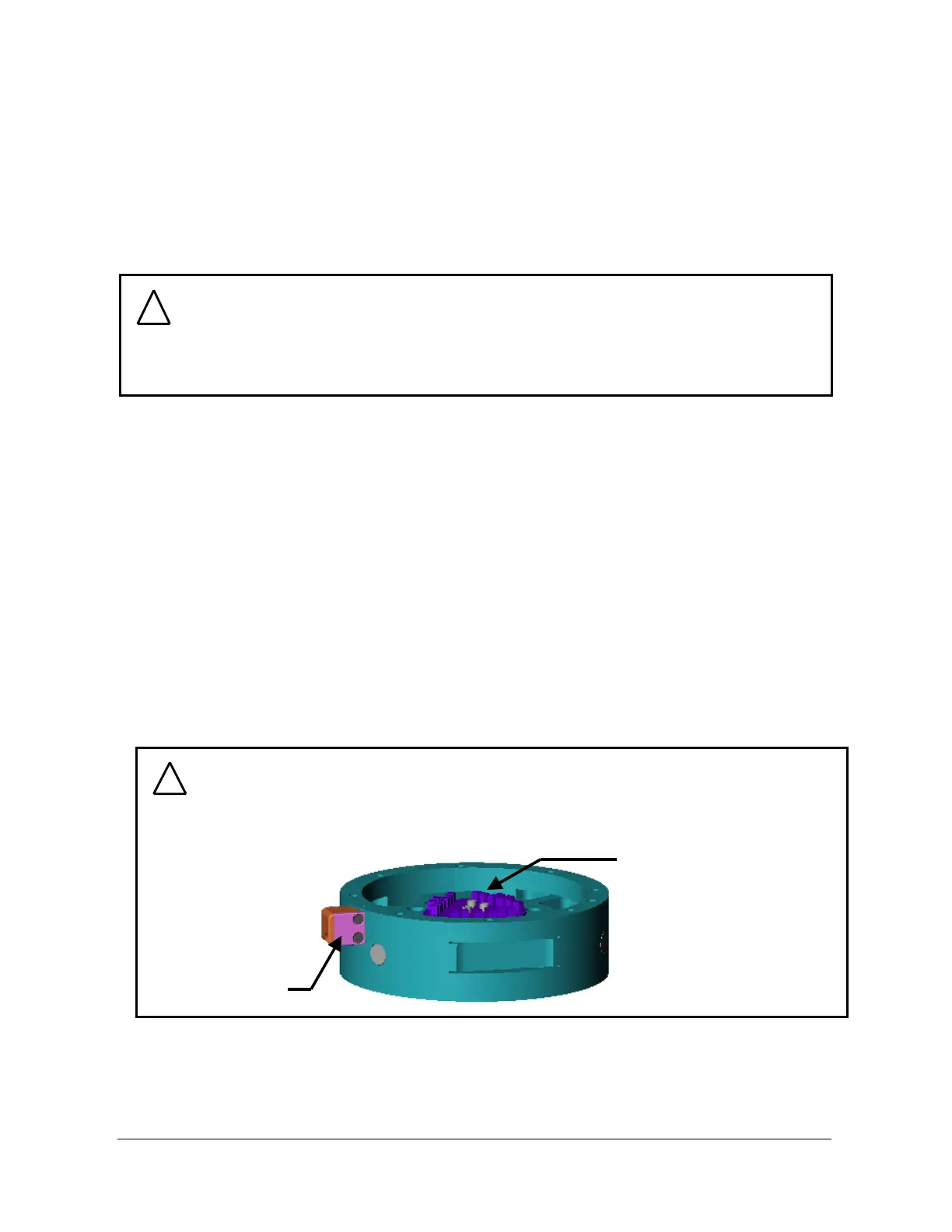
CAUTION: The transducer, Power Supply box, Interface Power Supply box, and
DAQ card are susceptible to damage from electrostatic discharge whenever they
are not connected to a plugged-in computer. Do not touch the electronics or the
connector pins when handling the transducer.
Connector
On-Board
Electronics
Connector
On-Board
Electronics
!