F/T DAQ Installation and Operation Manual
Document #9610-05-1017-06
ATI Industrial Automation, 1031 Goodworth Drive, Apex, NC 27539 USA +1-919-772-0115 www.ati-ia.com
18
- Machine the mounting adaptor plate for attaching to your robot (or other device).
Mounting adaptor plate dimensions are shown in Appendix B, Mechanical Layout [see
Figure 2.1]. All user-supplied screws must be flush with the inside of the mounting
adaptor to ensure proper clearance for the electronics inside the transducer.
- Attach the mounting adaptor to the robot (or other device). Attach the transducer to the
mounting adaptor with the screws and dowel pin provided. Thread locker is
recommended to prevent the screws from backing out due to vibration (e.g. Loctite
thread locker No. 222).
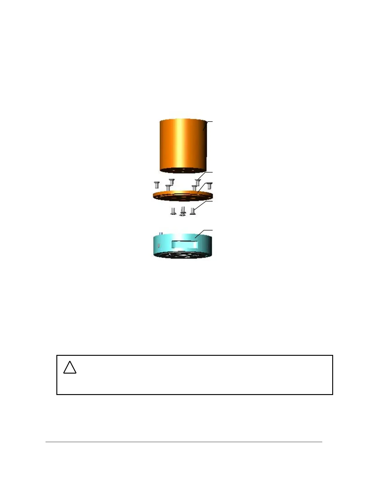
Figure 2.1—Attaching the transducer with the mounting adaptor plate
2.3.2 Transducer Mounting Method II:
Use your own interface plate to bolt directly to the transducer or (for the Nano, Mini or
Omega models) the mounting adaptor.
Use Appendix B, Mechanical Layout, for detailed mechanical drawings of the transducer and
all interface plates. Detailed descriptions of each method are shown on the next two pages.
Robot (or other device)
with threaded bolt circle
Mounting screws provided
Mounting adaptor plate
User-supplied flat head
screws
Transducer
Mounting side
Tool side
CAUTION: Do not attempt to drill, tap, machine, or otherwise modify the
transducer. This could damage the transducer and will void the warranty. Do not
attempt to remove any part of Nano, Mini, or Omega model transducers as
damage will occur.
!