F/T DAQ Installation and Operation Manual
Document #9610-05-1017-06
ATI Industrial Automation, 1031 Goodworth Drive, Apex, NC 27539 USA +1-919-772-0115 www.ati-ia.com
17
2. Installation
2.1 Introduction
This section will assist the user in mounting the transducer, tooling, and the transducer cable.
2.2 Routing the Transducer Cable
The transducer cable must be routed so that it is not stressed, pulled, kinked, cut, or
otherwise damaged throughout the full range of motion. See Section 1.4 for the transducer
cable interfacing. If the desired application results in the cable rubbing then use a plastic
spiral wrap for protection.
2.3 Mounting the Transducer
There are two different Methods, I and II, for mounting most F/T transducers. Mount the
transducer to a structure with sufficient mechanical strength. Not doing so can lead to sub-
optimum performance. The Nano, Mini and Omega transducers have mounting and tool
adaptors which cannot be removed, so only Method II can be used.
2.3.1 Transducer Mounting Method I:
Uses the standard mounting adaptor to attach the transducer. You must machine the bolt
pattern of your device (i.e. robot) into the mounting adaptor. You will not be able to use the
mounting adaptor alone if your device covers the mounting screws used to connect the
transducer. If this is the case, use Method II.
Use the mounting adaptor to attach the transducer as follows
- Ensure that you provide sufficient clearance between the mounted transducer and other
fixtures, and that total stack height is acceptable. Also ensure that after the mounting
adaptor is attached to the robot (or other device) you will have access to the mounting
screws for attaching the transducer.
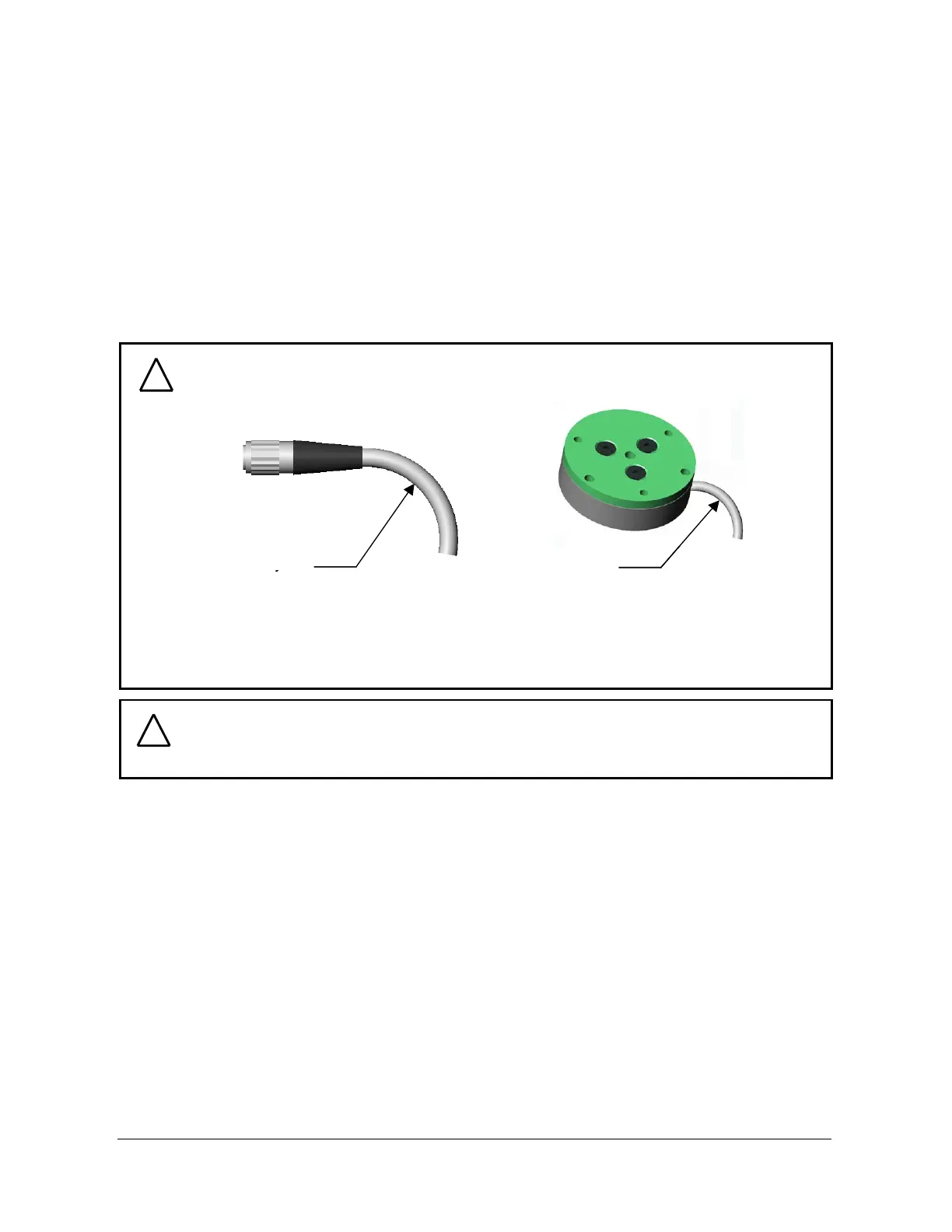
CAUTION: When a cable is cycling below the minimum bending radius, the cable
may fail due to fatigue. A smaller radius may be used if it is not being cycled.
Minimum cycled
bending radius 60mm
(at room temperature)
Minimum cycled
bending radius 40mm
(at room temperature)
Minimum cycled
bending radius 60mm
(at room temperature)
Minimum cycled
bending radius 60mm
(at room temperature)
Minimum cycled
bending radius 40mm
(at room temperature)
The minimum cycled bending radius is different with significant temperature
changes, increasing with lower temperature and decreasing for higher
temperature.
!
CAUTION: Be careful not to crush the cable by over-tightening tie wraps or
walking on the cable, since this may damage the cable.
!