F/T DAQ Installation and Operation Manual
Document #9610-05-1017-06
ATI Industrial Automation, 1031 Goodworth Drive, Apex, NC 27539 USA +1-919-772-0115 www.ati-ia.com
14
Windows
drivers, sample programs, C source code, and detailed help files. The most recent
release of the DAQ software can be found on the web at http://www.ati-
ia.com/download/software.htm.
1.3.7 Interface Plates
The larger transducers come with a standard mounting adaptor to mechanically attach the
transducer to your robot arm or apparatus that will be applying the force. The transducer also
has a standard tool adaptor with an ISO 9409-1interface for Gamma, Delta, and Theta models
for attaching your tool.
The mounting adaptor consists of:
- Mounting adaptor plate
- Mounting screws
For further information not in this section see:
- Section 2, Installation
- Appendix B, Mechanical Layout
1.4 Connecting the System Components
1.4.1 Connecting the Transducer Cable
Large DAQ F/T transducers connect to the system through a high-density 20-pin connector.
(see Figure 1.3). The Nano and Mini F/Ts have integral cables.
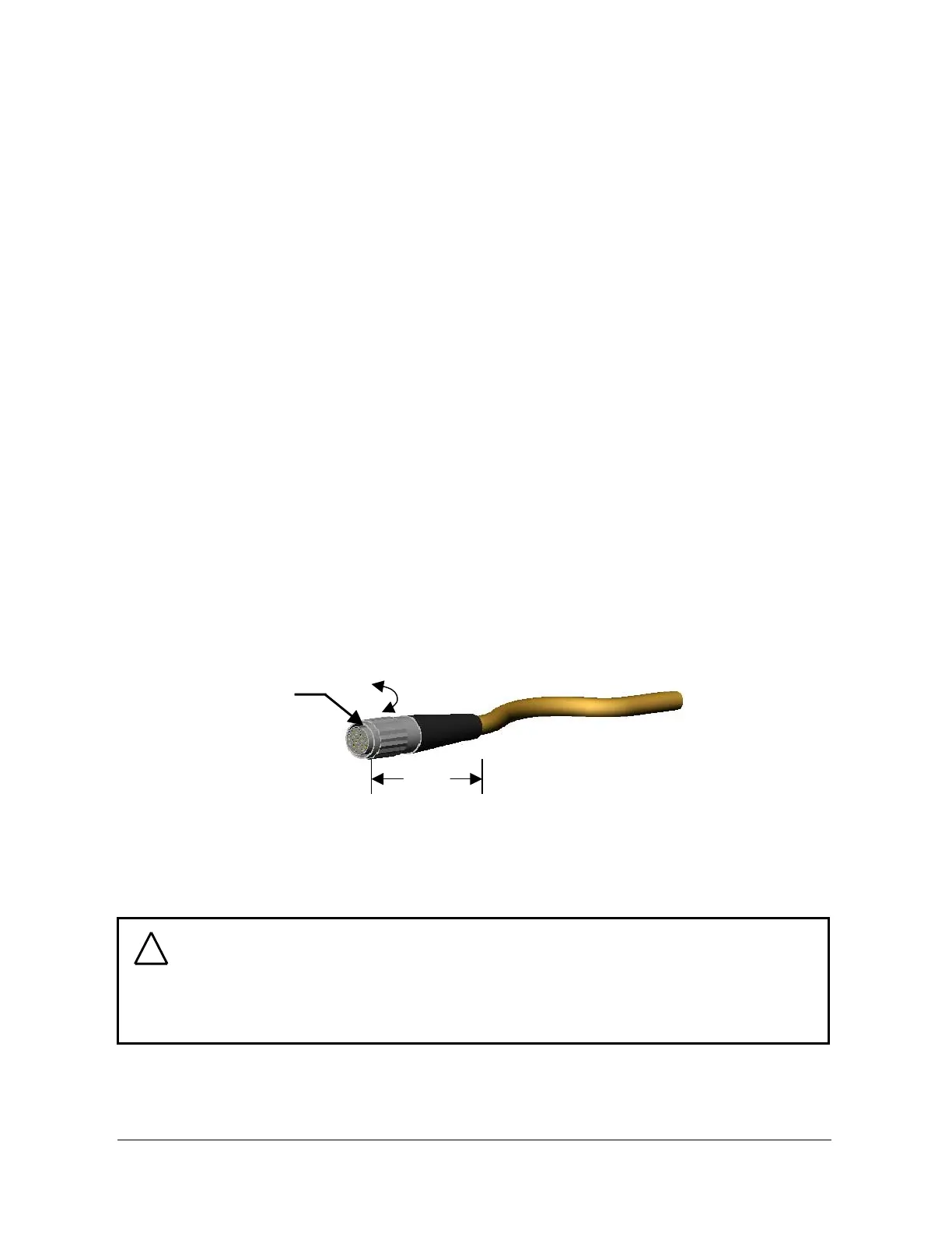
Connect the transducer cable connector to the transducer as follows:
- Lightly place the connector into port on the transducer. Do not push.
- Line up the groove on the connector to the key in the port by rotating the connector
while lightly forcing the connector into the port. When the groove lines up the connector
will go noticeably deeper into the port.
- Screw the connector shell into the transducer until it seats firmly.
Figure 1.4—Transducer Connector
Disconnect the transducer connector from the transducer port by unscrewing the connector
shell.
1.4.2 Installing the Data Acquisition Hardware
Install the data acquisition hardware and its accompanying software following the instructions
included with the hardware.
CAUTION:
Cables on the Nano and Mini transducers are permanently attached to the
transducer and can not be disconnected. Do not attempt to disassemble these
transducers as damage will occur.
!
1.5 in.
(38mm)
Turns to Mate
and Unmate