9
O&M Manual (Rev-H)
Part 2 – Mechanical Installation
2.1 Transmitter Mounting
Threaded inserts in the rear of the enclosure permit the attachment of brackets for securing the transmitter
to a wall or pipe. An optional bracket is also available for “flush mounting” the transmitter into a panel, so
that only the front cover protrudes. (This option is available for Remote AC powered units ONLY.
Choose a location so the transmitter display is readily visible, and the panel buttons and sensor are
accessible for calibrations. Consider the remote sensor option to locate the sensor closer to the source of
a potential gas leak, or closer to the floor for gasses heavier than air.
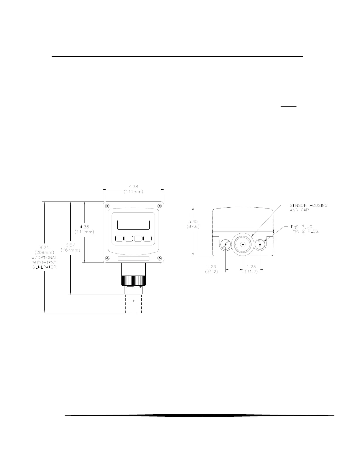
2.2 Enclosure Dimensions
Dimensions and the conduit entry locations are detailed in Figure 2 below.
Figure 2. Enclosure dimensions, (RS485 no relays)