Home
ATI Technologies
Transmitter
F12/D
Page 33 (Sensor Review)
ATI Technologies F12/D - Sensor Review
86 pages
Manual
Save Page as PDF
To Next Page
To Next Page
To Previous Page
To Previous Page
Loading...
ATI
Model F12
/D
Gas Transmitter
Part 4
–
Operation
32
O&M Manual (Rev-H
)
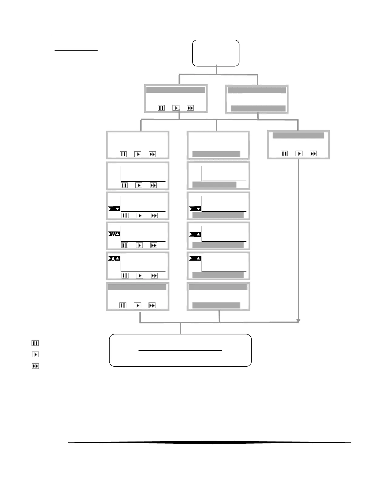
Sensor Review
Review Control Icons
Pauses the d
isplay
Skips to t
he next display
Skips to t
he Main Display
Operator Verify
Review pau
ses indefinite
ly at: Verify SIB,
Verify Se
nsor, Verify Range, Ver
ify C-
Alarm, Verify
W-Alarm, Verify A-Alar
m,
and Clear Dat
alog, The Trouble a
larm is
activate
d after 5 minutes o
f no keypad
activity.
ATi Gas
Xmtr
SIB
-8-1-1
►
Verify SIB
Start
(Same Type Se
nsor)
(New Type Sen
sor)
24.2 H2S
Range= 10 PPM
To 200 PPM
►
PPM
H2S
►
50
PPM
H2S
►
Verify Range
50
24.2 H2S
Range= 10 PPM
To 200 PPM
►
Verify Sensor
PPM
H2S
►
-10.0
C
A
PPM
H2S
►
20.0
PPM
H2S
►
Verify A-Alarm
20.0
A
PPM
H2S
►
Verify C-Alarm
C
-10.0
W
PPM
H2S
►
10.0
PPM
H2S
►
Verify W-Alarm
W
10.0
Sensor Trouble
Sensor Removed
Cannot Install
►
Programmed rang
e,
units and gas na
me
Caution alar
m level
Warning alarm leve
l
Alarm level
ATi Gas Xmtr
SIB
-8-1-1
►
SIB
–
model-
rev
-
id
Gas number, na
me,
units, and range
limits
Data logger statu
s
and usage
Data Log Status
Logging is ON
<n> days of 11
►
Clear Datalog
The Datalog is
specific to the
sensor gas typ
e
and range.
Data Log Status
Active = Yes
<n> days of 11
►
(Sensor Missing)
Figure
32
. Sensor Review Display
(Same SIB)
(New SIB)
32
34
Table of Contents
Main Page
Table of Contents
2
Safety
5
Warnings
5
Hazardous Location Installation
5
Part1 - Introduction
6
General
6
Figure 1- Transmitter W /Sensor
6
H10 Smart Sensors
7
Specifications
9
Part 2 - Mechanical Installation
10
Transmitter Mounting
10
Enclosure Dimensions
10
Figure 2. Enclosure Dimensions
10
Wall and Pipe Mounting
11
Figure 3 Deep Enclosure Dimensions
11
Figure 4 Wall/Pipe Mounting Bracket
11
Figure 5. Wall Mounting Diagram
12
Figure 6. Pipe Mounting Diagram
12
Panel Mounting
13
Duct Sensor Mounting
13
Sensors Only )
13
Figure 7. Panel Mounting Details
13
Figure 9. Duct-Mount Assembly
14
Duct Mount (Integral)
15
Generator Installation /R
15
Emoval
15
Figure 10 - Duct Mount
15
Figure 11 - Generator Explodedv
15
Part 3 - Electrical Connections
16
Transmitter Connections
16
Terminal Board - Sensor
17
Onnections
17
Figure 13. Sensor /Generatort
17
Terminal Board - Loopp
18
Figure 14. Power and Communication Terminals
18
Heated Sensor Housingw
19
Iring
19
Figure 15 - Heated Sensor Wiring
19
Remote Sensor Wiring
20
Figure 16 -Remote Sensor Wiring
20
Heated Sensor Wiring
21
Figure 17 -Remote Sensor Wiring
21
Heated Remote Sensorw
22
Iring (2-Wire )
22
Figure 18 - Heated Remotes
22
Duct Mount Sensorw
23
Sensor Connections with
23
Iring
23
T Cable
23
Figure 19 - Duct Mount Sensor
23
Figure 20 - Wiring Connections
23
Ac or
24
Figure 21 - Powered Alarm Relay
24
3.11 Relay Configuration
25
3.12 Remote Reset Input
25
Figure 22 - Relay Configuration
25
Figure 23 - Remote Reset Input
25
3.14 Wiring Examples
26
Ac or
27
Figure 25 - Ac or
27
Figure 53. S
27
Figure 63. T
27
Figure 64. O
27
Figure 66. L
27
Hart Point - to -Point
29
Ire )
29
Communications Jumper
30
Part 4 - Operation
31
4.1 Operator Interface Panel
31
Menus and Settings
31
Moving the Cursor and Selecting
31
Editing Settings
31
4.2 Startup
32
Transmitter Review
32
Figure 62. a
32
Figure 65. H
32
Sensor Review
33
Generator Review
34
Main Display
35
Main Reading
35
Trouble Indication
36
Timed Return to Main Display
36
Inhibiting Alarms from the Main Display
36
Displays
36
Sensor Removed Display
36
Sensor Installed
36
Figure 36. Main Display
36
Generator Removed
37
Generator Installed
37
Enu
38
4.5 Main Menu
38
Alarm Active Menu
38
Menus , Methods , and Settings
39
Sensor Menu
39
Sensor Settings Menu
39
Sensor Model Menu
39
Sensor Range Menu
40
Sensor Calibration
41
Sensor Calibration Menu
42
Figure 48. S
42
Figure 50. S
43
Figure 51 S
43
Figure 52. S
44
Sensor Auto-Test
45
Figure 54. a
46
Figure 55. a
46
Figure 56. a
46
Figure 57. a
47
Figure 59. G
48
Figure 60. a
48
Figure 85. G
48
Figure 89. a
48
Enus , Methods , and Settings
49
Alarms Menu
49
Gas Level Alarms
49
Figure 61. a
49
Figure 67. a
52
Figure 68. a
52
Figure 73. a
53
Figure 74. a
53
Trouble Alarm
54
Alarm Inhibit
58
Alarm Test Menu
59
Menus , Methods , and Settings
60
Data Log Menu
60
Data Log Setup Menu
61
Data Log View Menu
61
Figure 76. D
61
Figure 77. D
62
Figure 78. D
62
Data Log Print Menus, Methods, and Settings
63
Figure 79. D
63
Figure 80. D
63
Figure 81. D
64
Figure 82. D
64
Enus , Methods and Settings
65
I/O Menu
65
4-20Ma Output
65
Com Menus and Settings
67
Figure 88. a
67
Figure 93. H
70
Relay Operation, Menus, and Settings
71
Menus , Methods , and Settings
73
Panel Menu
73
Display Menu
73
Security Menu
74
Menu
78
Clock Menu
78
Reset Menu
78
Version Menu
79
Part 5 - Maintenance
80
Part 6 - Spare Parts
82
Figure 47. D
86
Figure 83. D
86
Figure 94. H
86
Figure 95. M
86
Figure 96 a
86
Related product manuals
ATI Technologies d12 series
92 pages
UniSens A12 Series
31 pages