ATI Model F12/D Gas Transmitter Part 2 – Mechanical Installation
10
O&M Manual (Rev-H)
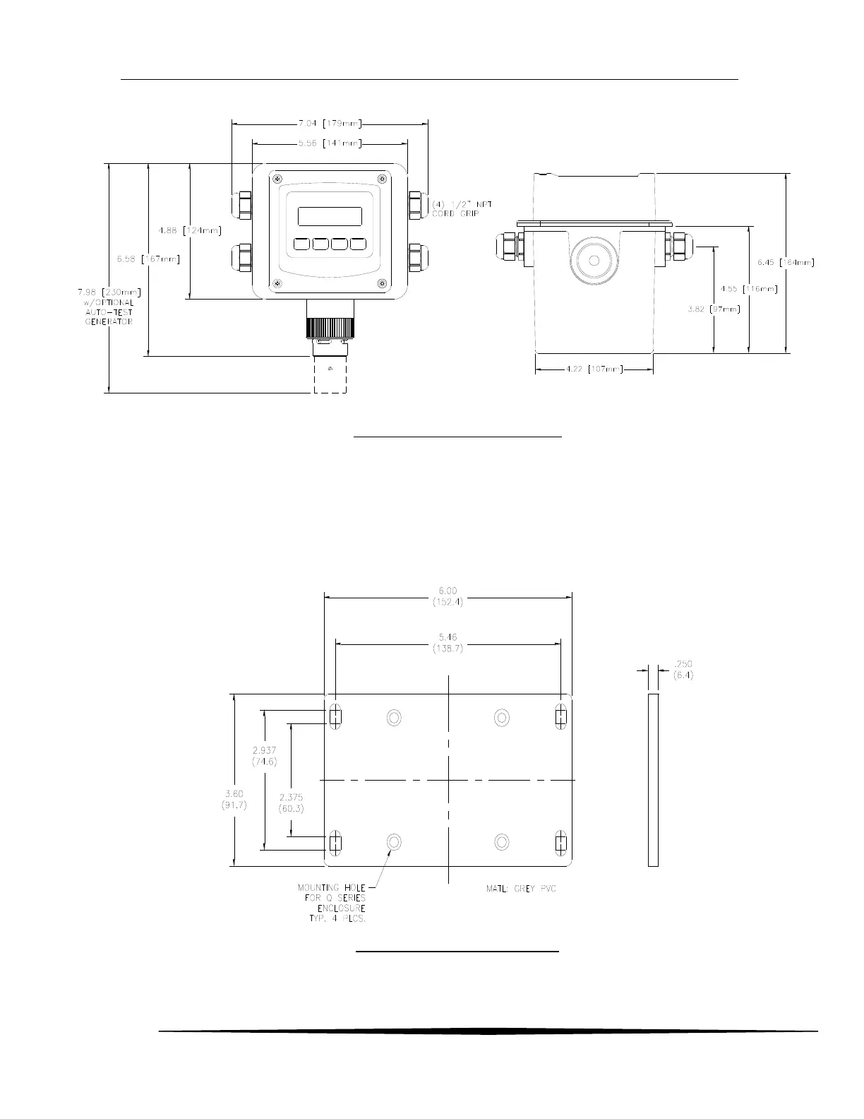
Figure 3 Deep Enclosure dimensions
2.3 Wall and Pipe Mounting
A PVC mounting bracket with attachment screws is supplied with the transmitter. The transmitter is
attached to the bracket using four flat head screws, and the bracket is attached to a wall or pipe by way of
the four slots in each corner. The slots will accommodate ¼” u-bolts designed for 1½”or 2” pipe. For 1 ½”
pipe, type 304 stainless steel u-bolts with 2” I.D. are available from ATI (p/n 47-0005).
Figure 4 Wall/pipe mounting bracket