15
O&M Manual (Rev-H)
Part 3 – Electrical Connections
3.1 Transmitter Connections
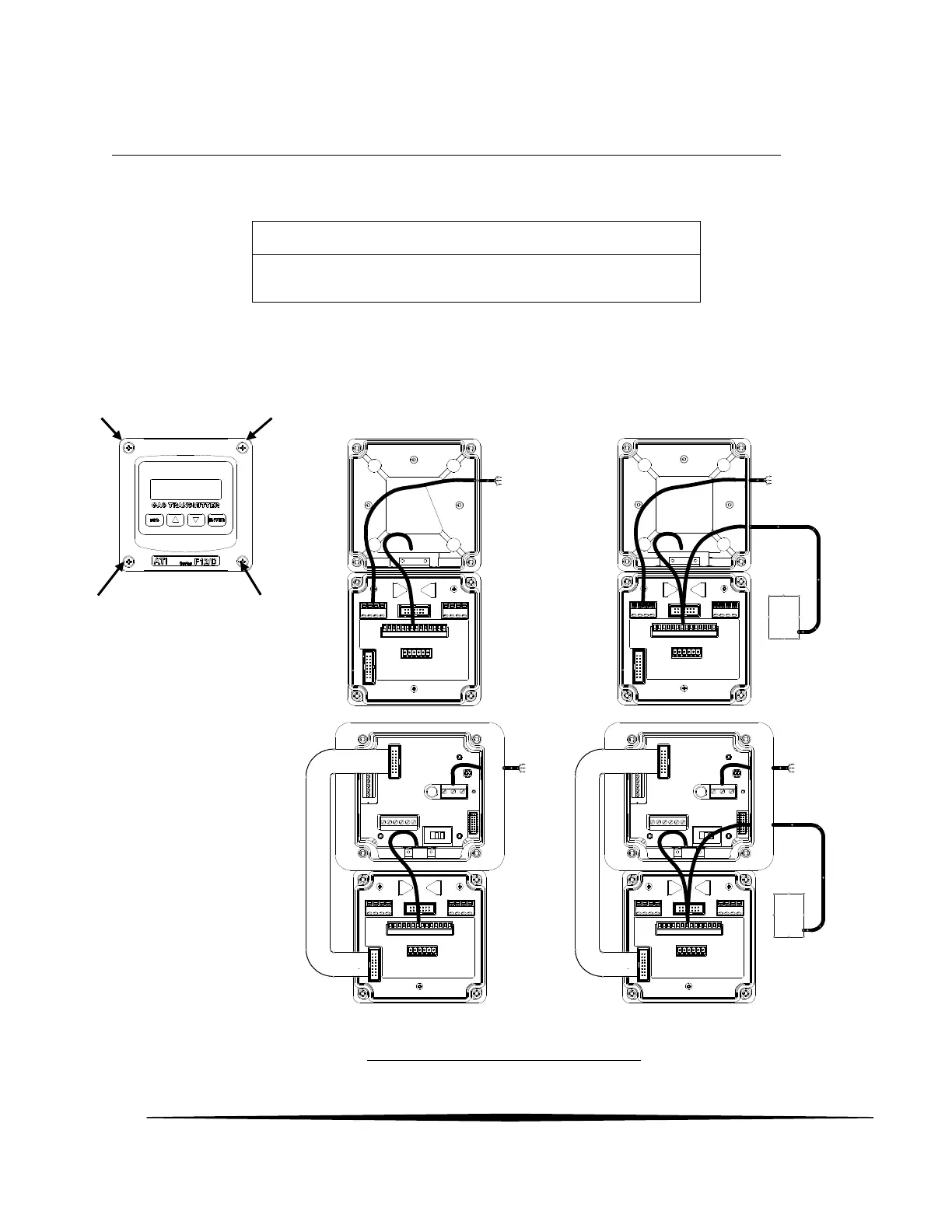
To access the wiring terminals inside the transmitter, loosen the four screws in each corner of the housing’s
front cover. The front cover is hinged to the rear cover along its lower edge so it will swing down and stop
at approximately 90°. The transmitter has limited space for wire; therefore, use the smallest gauge wire
available that is compatible with electrical code and current requirements.
AC or DC
12-30V
Powered
Transmitter
w/o Autotest
Generator
AC Mains
or
12-30V
Autotest
Generator
AC Mains
or
12-30V
Autotest
Generator
Loop Powered
Transmitter
w/o Autotest
Generator
Loop Powered
Transmitter
w/ Autotest
Generator
4-24 mA
LooP
4-24 mA
LooP
AC or DC
12-30V Powered
Transmitter
w/Autotest
Generator
Figure 12. F12/D Transmitter Configurations
Installation must be in accordance with the recognized standards of
the appropriate authority in the country concerned.