ATI Model F12/D Gas Transmitter Part 4 – Operation
64
O&M Manual (Rev-H)
An RS232 connection can support full duplex communication and is perfectly suited for XON/XOFF flow
control. However, an RS485 connection is only half duplex. It cannot receive while it is transmitting and
might miss the XOFF character, resulting in a buffer overflow at the receiving device.
A receiving device will send the XOFF character when its buffer is nearly full. Some older dot-matrix
printers will send an XOFF because they have a small receive buffers and cannot process characters
while the head is returning to start a new line. By comparison, most computers have comparatively large
buffers and can easily accept the report stream without sending an XOFF, so an RS485 connection may
work in those cases.
The transmitter features an additional method to help avoid losing data due to buffer overflow problems
on receiving devices that lack XON/XOFF capability (or have the capability but are using an RS485
connection). A programmable time delay of up to 10s may be inserted at the end of each report line.
This permits the receiver time to process more characters in its buffer and avoid an overflow. However,
this may be a method of trial and error until the proper delay setting is determined so that no characters
are missing from the report.
4.10 I/O Menus, Methods and Settings
I/O Menu
The I/O menu is shown below and appears by selecting I/O from the Main Menu on pg 37.
Figure 83. I/O Menu
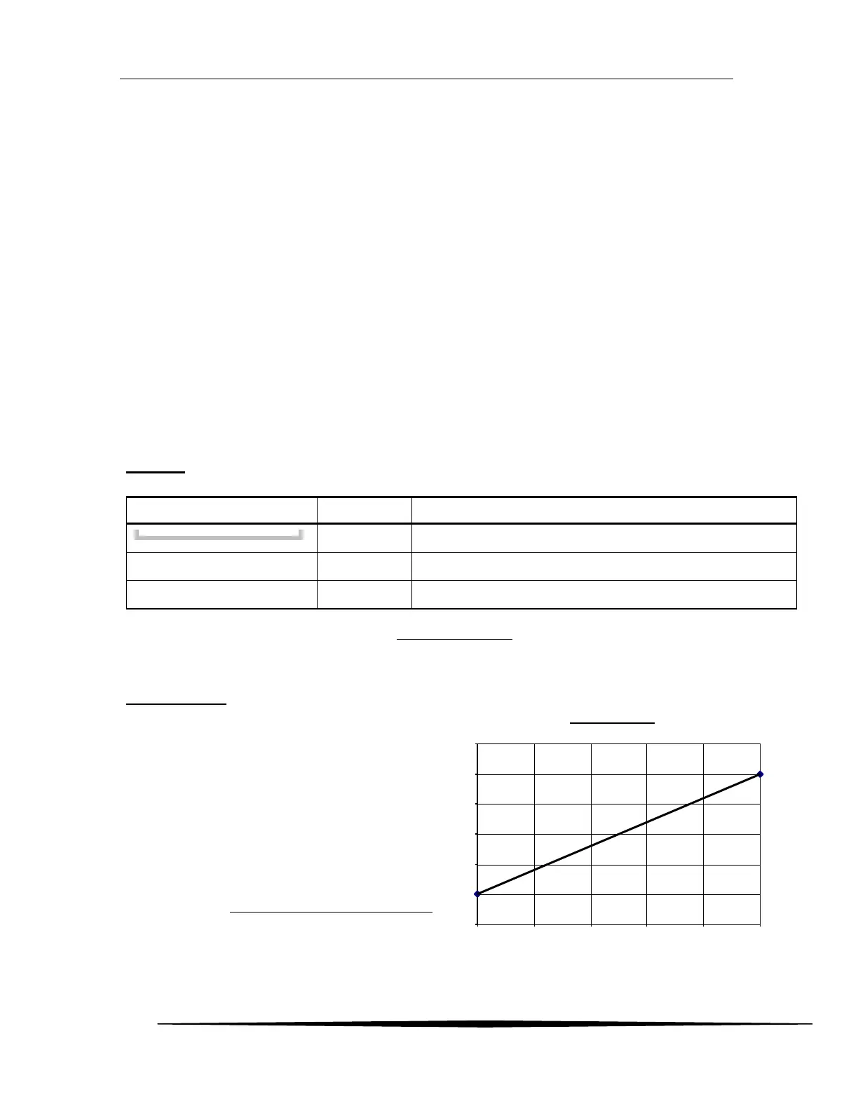
4-20mA Output
The transmitter sources (or sinks) a 4-20mA
current that is proportional to the gas reading on
the Main Display (see Main Reading on pg 34) .
The current is normally 4 mA at zero and 20mA
at the programmed range of the sensor (see
Range in Sensor Settings Menu on pg 38).
Since the Main Reading is blanked below zero,
the output should never go below 4mA in the
course of normal operation. In the event of gas
flooding, the current and may go as high as
25mA (125% Range).
Figure 84. Graph of 4-20mA Output
Configure and adjust the 4-20mA output.
Configure the RS232/RS485 serial interface (option).
Configure the three transmitter relays (option).