ATI Model F12/D Gas Transmitter Part 3 – Electrical Connections
21
O&M Manual (Rev-H)
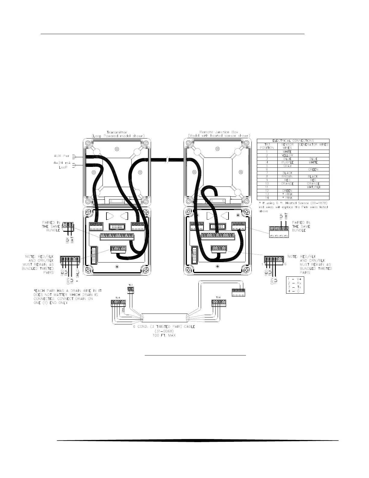
3.7 Heated Remote Sensor Wiring (2-Wire)
The heated remote sensor option requires an additional 2 wires between the transmitter and the remote
junction box. The interconnections are shown below.
Notes:
Rx of the Transmitter must be connected to Tx of the Junction box
Tx of the Transmitter must be connected to Rx of the Junction box
The shield must be connected only at one end. Preferably at the Transmitter end
Use shielded 6 conductor (3 twisted pairs) cable, or run the lines for the sensor heater separately
Figure 18 – Heated Remote Sensor wiring