EasyManuals Logo

ATI Technologies F12/D User Manual

Default Icon
86 pages
To Next Page IconTo Next Page
To Previous Page IconTo Previous Page
Page #20 background imageLoading...
Page #20 background image
ATI Model F12/D Gas Transmitter Part 3 Electrical Connections
19
O&M Manual (Rev-H)
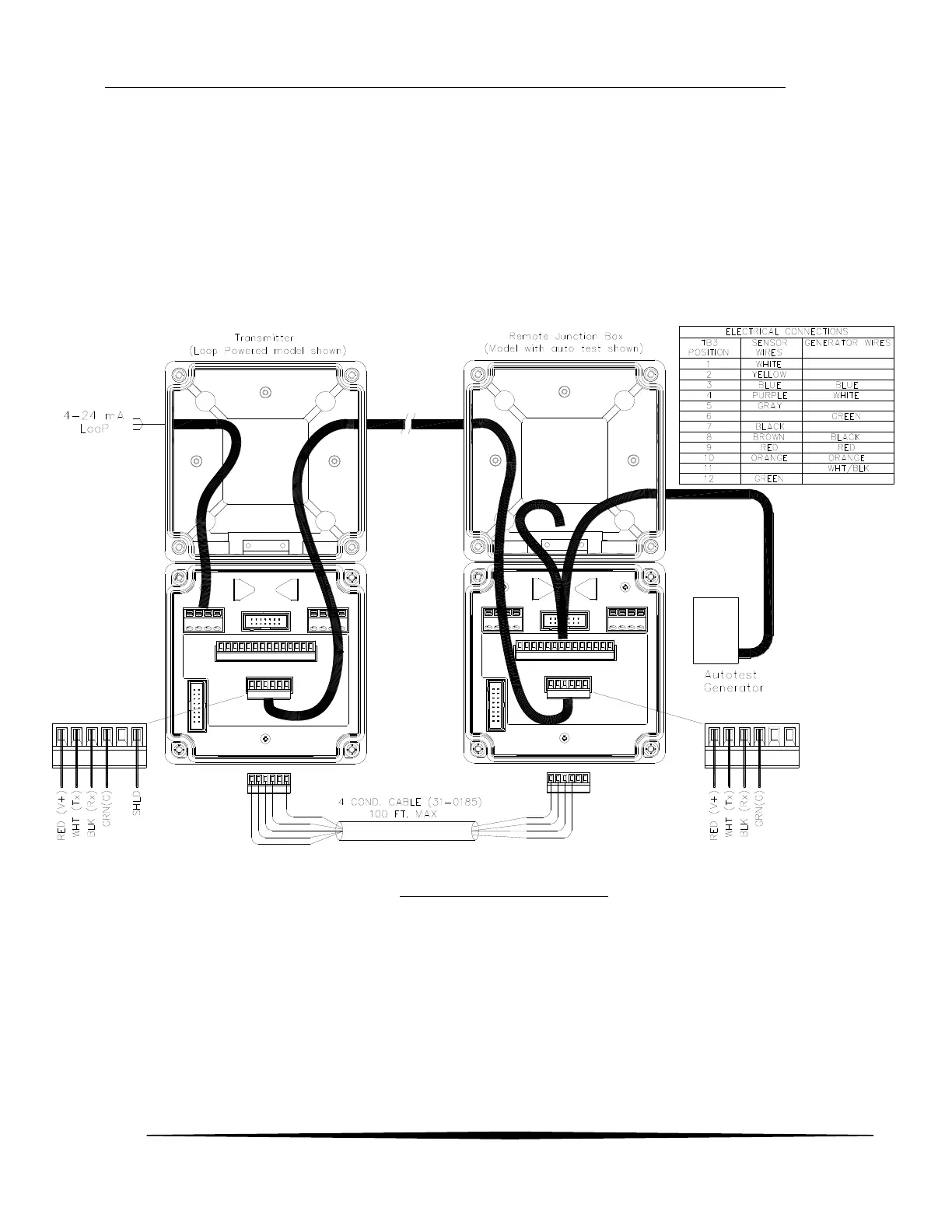
3.5 Remote Sensor Wiring
The remote sensor option permits the sensor to be mounted up to 100’ from the transmitter. Remote
interconnect cable sold separately. The interconnections are shown below.
Notes:
The shield must be connected only at one end. Preferably at the Transmitter end
Use shielded 4 conductor (2 twisted pairs) cable
Loop Powered model shown. Interconnections for AC and VDC powered models are similar to Loop
powered model.
Figure 16 Remote Sensor wiring

Table of Contents

Questions and Answers:

Question and Answer IconNeed help?

Do you have a question about the ATI Technologies F12/D and is the answer not in the manual?

ATI Technologies F12/D Specifications

General IconGeneral
BrandATI Technologies
ModelF12/D
CategoryTransmitter
LanguageEnglish