ATI Model F12/D Gas Transmitter Part 4 – Operation
70
O&M Manual (Rev-H)
More information about configuring the Modbus connection can be found in the table below.
Relay Operation, Menus, and Settings
The following applies to F12 transmitters ordered with optional 3 SPST relays that are NOT INTENDED for
Hazardous Locations.
The F12 Alarm Relay option provides three SPST mechanical relays on the Power Supply board. The
relays are rated for 5 amps, non-inductive loads at 250VAC, and are suitable for switching small loads,
such as horns and warning lights, but should not be used to switch motors or other high current, inductive
loads.
Each relay coil may be assigned to one of the four alarms and operate as normally energized (Norm=1,
also called “fail-safe”), or normally de-energized (Norm=0). Selecting normally energized (1) allows the
relay to indicate an alarm, or a power failure. This selection is made in the Relay Setup Menu on page
72.
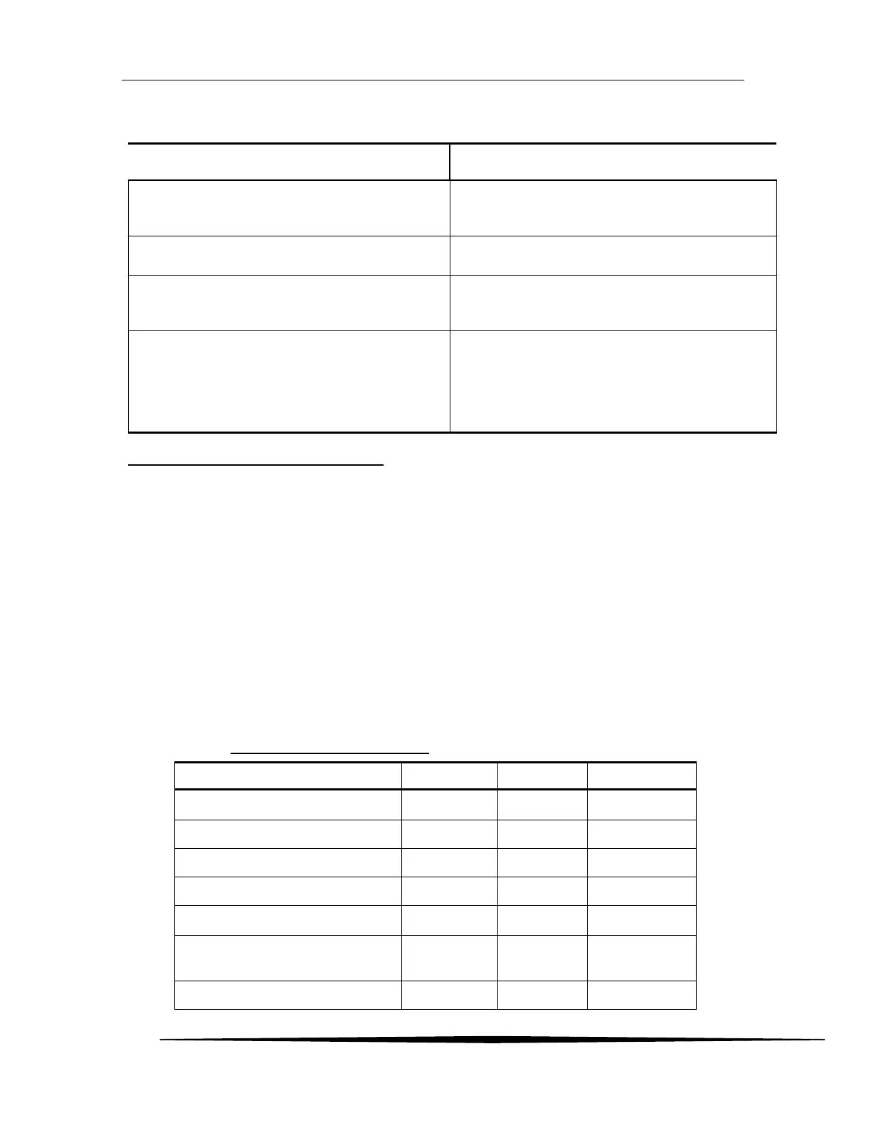
The table below details the contact states for the two selections in the no-alarm, alarm, and power fail
conditions.
Table 6. Relay Coil “Norm” Setting
Connect to a master using an RS485 multi-drop
connection.
Connect to a master using an RS232 connection.
Select Modbus protocol and configure the
communication settings.
COM Setup Menu on page 678
The transmitter’s Modbus interface is robust and
maintained in a separate document. Download or
request a copy of, “D12/F12 Series Modbus Interface
Manual”.
0 (normally de-energized)
1 (normally energized, “fail-safe”)