ATI Model F12/D Gas Transmitter Part 2 – Mechanical Installation
12
O&M Manual (Rev-H)
2.4 Panel Mounting (Remote Sensors Only)
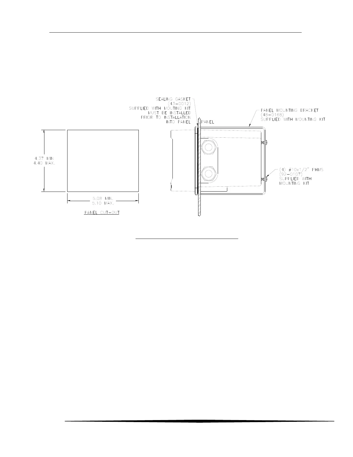
Figure 7 depicts the details for panel mounting the deep case. For this, a bracket attaches to the rear
housing, and when adjusted, pulls the transmitter’s flange down against the adhesive side of the gasket
supplied with the bracket (make certain to remove the protective paper first).
Figure 7. Panel mounting details [deep case]
2.5 Duct Sensor Mounting
The H10 sensor duct mount option allows sensors to be installed in a duct or pipe, and provides easy
access for service.
The assembly is comprised of a special H10 sensor holder that slides into the hollow duct mount
adapter (See Figure 9). The adapter has 1-1/2” MNPT threads on the insertion end, for securing it
to the duct or pipe, and a barb fitting for supplying calibration gas to the sensor. An interface cable
is provided to connect the sensor holder to the transmitter. Note that a mating flange for securing
the adapter is not provided.
Screw the adapter into the duct or pipe so the barb fitting is accessible to connect gas tubing. Once
the adapter is in place, slide in the sensor holder, lock it in place, and connect the interface cable. It
is recommended that the sensor not be installed in the holder until you are ready to start the
transmitter. This is especially true during construction, when excessive dust and dirt may be blowing
through the duct system and be deposited on the sensor.