EasyManuals Logo

ATI Technologies F12/D User Manual

Default Icon
86 pages
To Next Page IconTo Next Page
To Previous Page IconTo Previous Page
Page #17 background imageLoading...
Page #17 background image
ATI Model F12/D Gas Transmitter Part 3 Electrical Connections
16
O&M Manual (Rev-H)
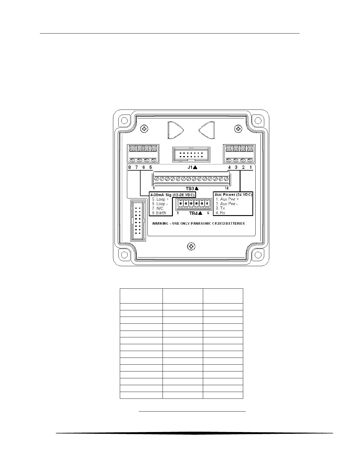
3.2 Terminal Board - Sensor Connections
The Terminal Board is located just below the metal shield in the front cover. It contains the power and
communication terminals, and provides a header for connecting the Sensor Housing wires and optional
Autotest Generator wires.
The table below lists connections for the Sensor Housing and Autotest Generator wires.
Conductor colors
TB 3
Position
Sensor
Wires
Generator
Wires
1
WHITE
2
YELLOW
3
BLUE
BLUE
4
PURPLE
WHITE
5
GRAY
6
GREEN
7
BLACK
8
BROWN
BLACK
9
RED
RED
10
ORANGE
ORANGE
11
WHT / BLK
12
GREEN
13
PINK or RED
14
PINK or RED
Figure 13. Sensor/Generator Terminal Wiring
Position 13 & 14 are for Heated
Sensor option. Colors will vary
depending on heated style
ordered

Table of Contents

Questions and Answers:

Question and Answer IconNeed help?

Do you have a question about the ATI Technologies F12/D and is the answer not in the manual?

ATI Technologies F12/D Specifications

General IconGeneral
BrandATI Technologies
ModelF12/D
CategoryTransmitter
LanguageEnglish