ATI Model F12/D Gas Transmitter Part 3 – Electrical Connections
20
O&M Manual (Rev-H)
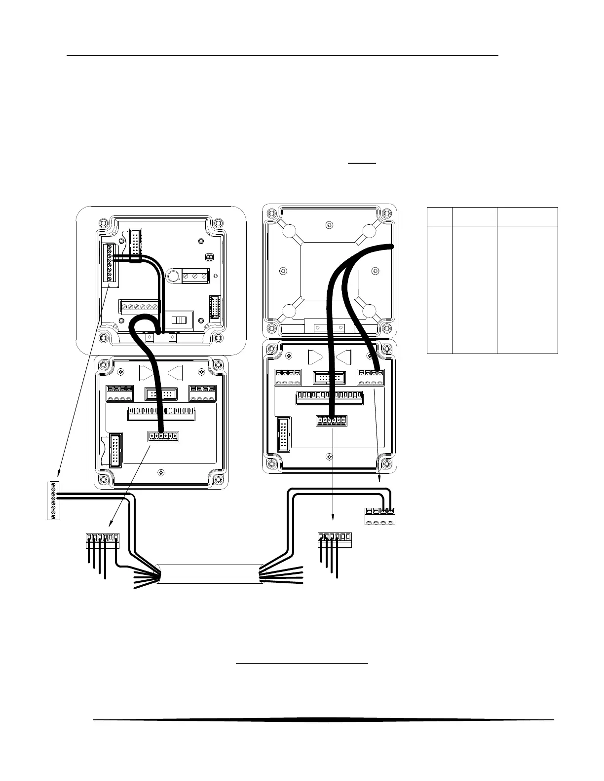
3.6 Heated Sensor Wiring (AC or VDC Powered) - Remote
The heated remote sensor option requires an additional 2 wires between the transmitter and the remote
junction box. The interconnections are shown below.
Notes:
The shield must be connected only at one end. Preferably at the Transmitter end
Use shielded 6 conductor (3 twisted pairs) cable (Pairs MUST stay together), or run the lines for the
sensor heater separately
TB4
TB3 141
12345678
J4a
TB6
GN
L
RL3RL2RL1
2
3
4
5
6
7
1
8
Junction Box
WHT (AUX -)
BLK
(AUX +)
WHT (HTR -)
BLK (HTR +)
TB4
TB4
B
L
K
(G
)
G
R
N
(R
x
)
B
L
K
(T
x
)
R
E
D
(V
+
)
S
h
ld
2
3
4
5
6
7
1
8
2
3
4
5
6
7
1
8
2
3
4
5
6
7
1
8
AC or 12/24 VDC Transmitter
EACH PAIR HAS A DRAIN
WIRE IN IT
DOES NOT MATTER WHICH
DRAIN IS CONNECTED DRAIN
ON (1) END ONLY
6 COND. (3 TWISTED PAIR) CABLE
(31-0068)
100 FT. MAX.
B
L
K
(G
)
G
R
N
(R
x
)
B
L
K
(T
x
)
R
E
D
(V
+
)
Figure 17 –Remote Sensor wiring
1
2
3
4
5
6
7
8
9
10
11
12
13
14
WHITE
YELLOW
BLUE
PURPLE
GRAY
BLACK
BROWN
RED
ORANGE
GREEN
*PINK
*PINK
BLUE
WHITE
GREEN
BLACK
RED
ORANGE
WHT/BLK
*If using the 6 ft. Heated
Sensor (00-1878), Red wires
will replace the Pink wires
listed above