ATI Model F12/D Gas Transmitter Part 3 – Electrical Connections
17
O&M Manual (Rev-H)
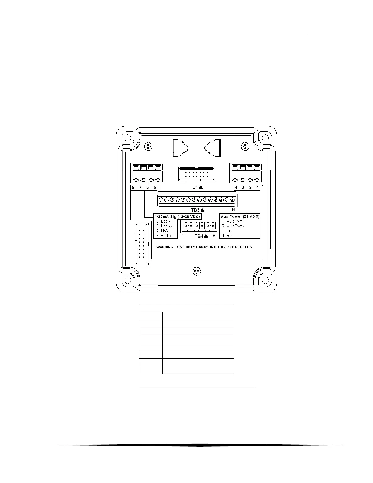
3.3 Terminal Board – Loop Power Connections
The Loop Powered transmitter model is powered in using terminals 5 and 6 commonly referred to as “two-
wire mode”.
Loop Powered models with the heated sensor housing and/or MODBUS communications option require an
additional 24 VDC supply to power them. This auxiliary power is connected to terminals 1 and 2.
Note: Connections to the communications on the DC Powered models are made on the power supply
board.
Figure 14. Power and communication terminals.