ATI Model F12/D Gas Transmitter Part 3 – Electrical Connections
28
O&M Manual (Rev-H)
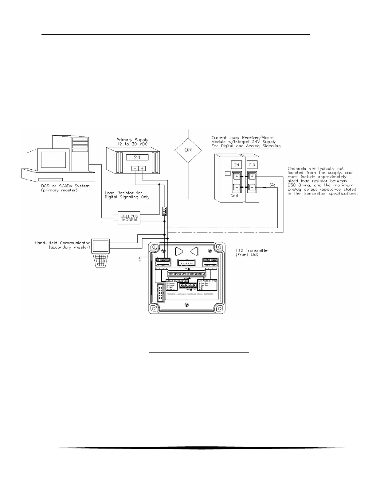
3.16 HART Point-to-Point (2-Wire)
The HART “Point-to-Point” connection permits the transmitter to communicate digitally, while retaining the
functionality of its 4-20mA current loop. Setting the transmitter’s polling address to 0 permits the current
loop to function normally. According to HART specifications, the current loop must be terminated with a
load resistor between 230 and 1100 ohms; however, transmitter specifications restrict the maximum analog
output resistance to a lower value (see Specifications). The term, “active source”, refers to a transmitter
that is not loop powered, and sources current from power applied to it on separate terminals. Size the
power supply according to the number of transmitters, the current demand of each transmitter (see
specifications), and wire resistance. Wire resistance must not be allowed to drop the Primary Supply
Voltage below 10V at the terminals of any transmitter. Hint: use at least 14 AWG wire on supply connections
(shown in bold).
Figure 27 - HART Point-to-Point (2-Wire)