ATI Model F12/D Gas Transmitter Part 3 – Electrical Connections
24
O&M Manual (Rev-H)
3.11 Relay Configuration
By default, RL1 and RL2 are under the control of the transmitter’s gas concentration alarms. The C
(common) and NO (normally open) contacts of relays RL1 and RL2 are jumpered to TB3 and are open
when their respective coils are de-energized (i.e., no gas alarm or no power). In contrast, RL3 is under the
control of the transmitter’s fault alarm, which is programmed to keep the relay coil energized until a fault is
detected (or power fails). The C and NC (normally closed) contacts of relay RL3 are jumpered to TB3 so it
is closed when the coil is de-energized. The default configuration may be modified cutting and reconnecting
jumpers on the Alarm Relay board, and by changing variables via the operator interface.
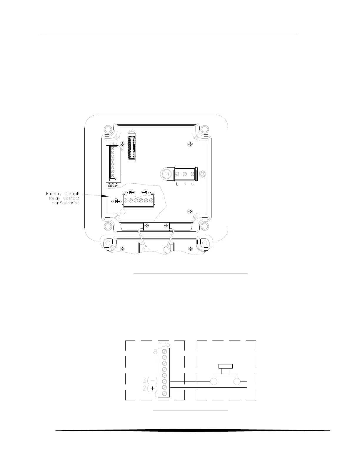
Figure 22 - Relay Configuration Jumper Location
Relays are best used as pilot relays if heavy load switching is desired. Use suitable arc suppression devices
across loads switched through internal relays.
3.12 Remote Reset Input
The remote reset inputs on pins 2 and 3 of TB5 are used to clear alarms requiring manual reset. The
function is activated when the two contacts are momentarily shorted together.
Figure 23 – Remote Reset Input