Appendix A - Changing Mains Voltage Selection
The ATS-1 Access is configured at the factory for the line voltage at its
intended destination, so usually the voltage will be correct unless the
unit has been transported into another area. This appendix describes
the procedure for changing the voltage setting, which may be
necessary under some circumstances.
Checking the Selected Line Voltage
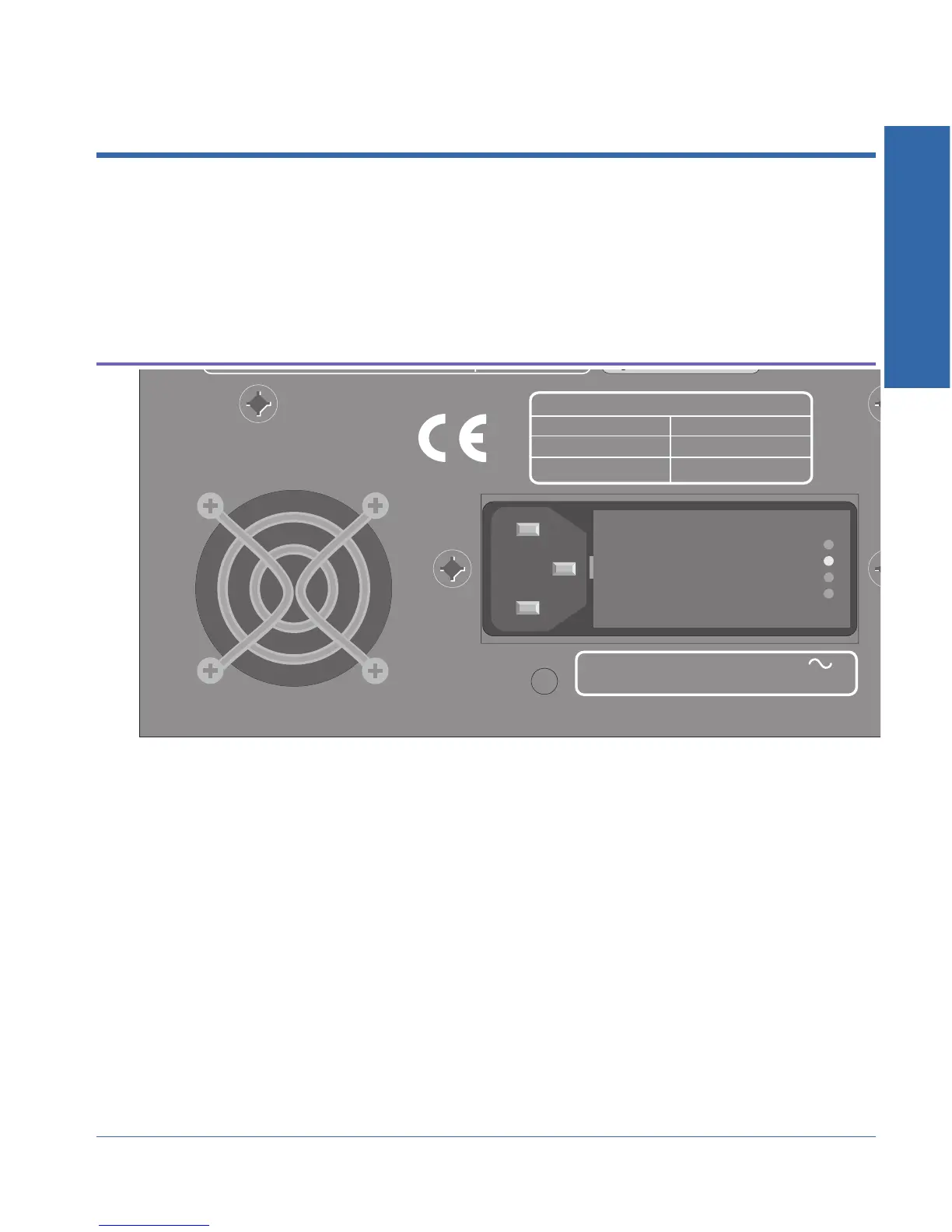
The supply voltage indicator is located on the rear panel of the
instrument next to the power plug. A small white plastic indicator tip
identifies the line voltage setting as 100V, 120V, 230V, or 240 V.
The following diagram shows the location of the voltage indicators:
In one of the holes should be a small white plastic indicator tip
showing which line voltage is currently selected. If the selected voltage
is not the same as the desired line voltage, continue with the next
section.
250mA T/SB 250V
500mA T/SB 250V
FREQUENCY: 50/60 Hz MAXIMUM POWER: 60 VA
SUPPLY VOLTAGE: 100/120/230/240 VAC
FUSE REPLACEMENT DATA
230/240 VAC
100/120 VAC
SUPPLY VOLTAGE FUSE