To obtain the specified accuracy, analog inputs must have amplitude
greater than about 20 mV and must have signal-to-noise ratio greater
than about 40 dB. If either input drops below about 8 mV (or below
10% of the selected fixed input range when the bargraph
HOLDRANGE function is used) the display will show the word Low,
and there will be no phase reading. If the S/N ratio in either channel is
less than 40 dB, the reading may be unstable, especially at low
frequencies.
IMD
The IMD measurement function is selected by pressing the FUNCTION
IMD button. It is only available if the Intermodulation Distortion
Option is installed. The ATS-1 Access can be purchased with or
without this option, or the option can be added at a later time.
The IMD measurement conforms to the SMPTE and DIN testing
standards. These standards call for a low-frequency tone to be mixed
with a high-frequency tone at a 4:1 amplitude ratio. The signal is then
sent through the device under test. Next, the low-frequency tone is
filtered out and the high-frequency tone is sent through an AM
demodulator. After bandwidth-liming to 700 Hz, the demodulated
signal is measured. This is the intermodulation distortion. It is
measured as a percentage or dB difference between the amplitudes of
the high-frequency tone and the demodulated remainder.
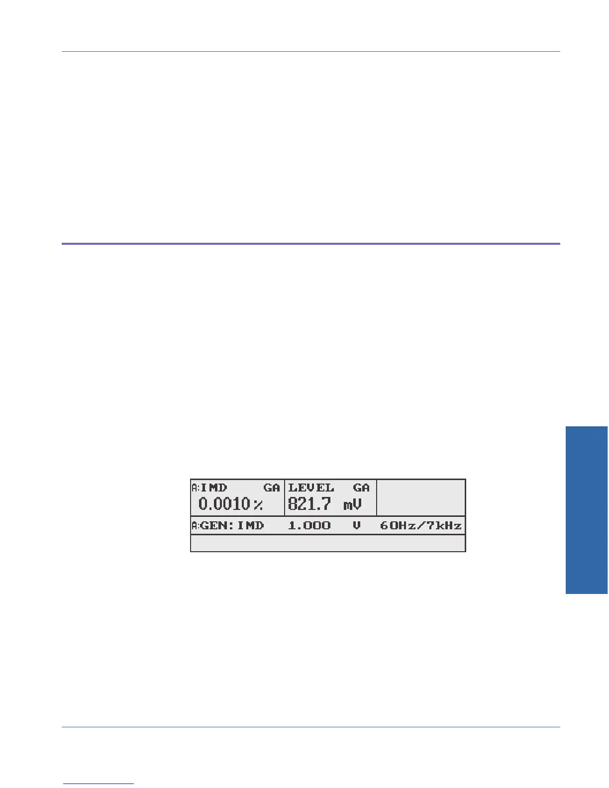
The upper left corner of the display shows the IMD reading. The units
may be selected from % or dB by pressing the top left soft key. The
upper center of the display shows the amplitude of the signal before
filtering. Pressing the top center soft key selects the units.
The IMD generator waveform is automatically selected when entering
IMD measurement function. You may then change the generator
waveform if desired, but this will result in an invalid IMD reading.
Figure 4-23. Main panel in IMD function
& For more
information on
HOLDRANGE, see page
.4-41
& For more
information on
amplitude units, ee
page 3-17.
4 Functions
Function Descriptions IMD
ATS-1Access User's Manual 4-27