Generator Loading
When a voltage unit (any unit besides dBm) is used, the generator
amplitude shown on the panel is the open-circuit voltage. Unless there
is no external load, the actual voltage at the load will be less than the
open-circuit voltage, since the selected source (output) impedance and
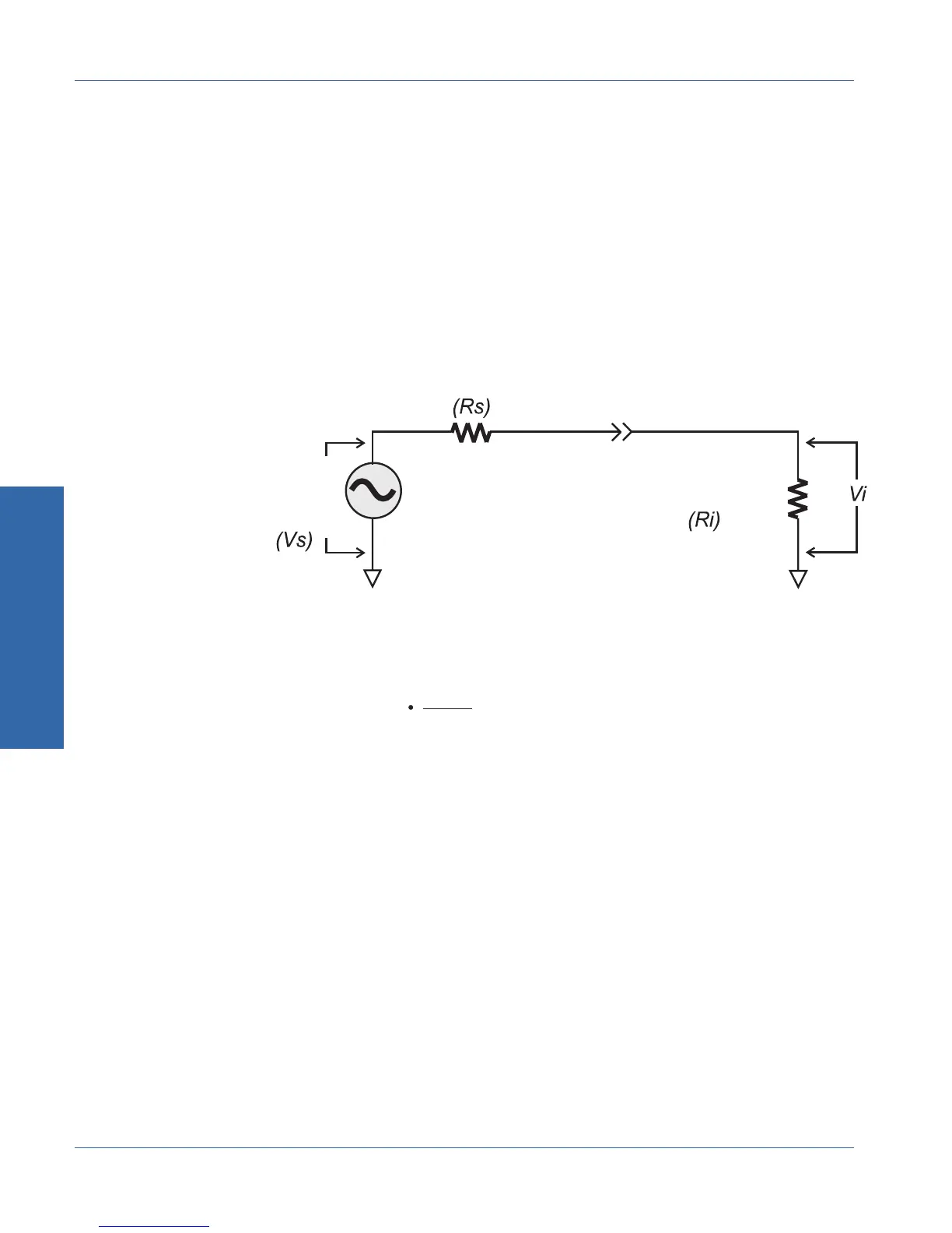
the impedance of the load will act as a voltage divider. The following
simplified schematic shows this relationship:
The voltage that will appear across the load can be calculated using the
following formula:
where Vi is the voltage across the load, Vs is the source voltage, Ri is
the input impedance of the DUT, and Rs is the source impedance. For
example, if you output a 1 volt signal using the 50 Ω source
impedance and load it with the analyzer’s 100 kΩ load, the voltage
across the DUT input will be 0.9995 volts. As long as the load is 4 kΩ
or higher, and the 50 Ω source impedance is used, the load voltage
will differ from the open-circuit voltage by no more than 0.1 dB. For a
100 kΩ load, typical of many professional audio devices, the 50 Ω
source impedance will cause an error of about 0.05 dB.
The dBm unit is a unit of power, not voltage. However, the generator
is always set in open-circuit voltage. When you are using the dBm unit
for generator output, the generator will be set to a voltage that would
cause the specified power (in dBm) to be dissipated in a load of
Vi = Vs
Ri
Ri +
Generator
Source
Impedance
DUT's Input
Load Resistance
Generator
Source
Voltage
Generator
Output
Connector
Figure 3-10. Source and Load Impedances
& For a more
detailed diagram of
the generator output
circuit, see page 1-13.
3 Operation
Controlling the Generator Operational Overview
3-14 ATS-1 Access User's Manual