External Connections
How a device is set up for testing depends on the type and function of
the device.
Analog Inputs and Outputs
Electrical connections between a device under test and the test
instrument are typically made with test cables. Analog test cables for
the ATS-1 Access should have appropriate connectors on both ends
for connection to the test instrument. Adapters may be used to adapt
a standard cable to the device or test instrument.
When cables or adapters for unbalanced connectors are used with an
XLR connector panel, pin 2 of the XLR connector should connect to
the signal conductor and pin 3 of the XLR connector should connect to
the ground. Also be sure to select an unbalanced generator
configuration (see page 3-29).
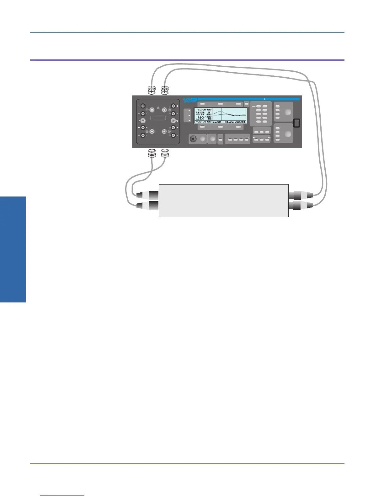
The ATS-1 Access’ Generator Outputs should be connected to the
analog inputs of the device under test. The Analyzer Inputs should be
connected to the analog outputs of the device under test.
DEVI
T
Left Channel Analog Input
Right Channel Analog Input
Left Channel Analog Output
Right Channel Analog Output
FRONT PANEL
ATS- Access Audio Test System
.
.
10
AMPLITUDE
DEC
+10dB
INC
-10dB
FREQUENCY
-10
INC
x
DEC
dBr ZERO
FUNCTION
LEVEL
AMPL
NOISE
THD+N
SINAD
PHASE
RATIO
XTALK
GEN
LOAD
IMD
W+F
AC MAINS
CHECK
GEN
AB
INPUT
INSTRUMENT MODE
OUTPUT
A
MUTE
B
PRINT
PANELS BARGRAPH SWEEP
MONITOR
CONTRAST
RECALL
SAVE
POWER
ADDR
REM
SRQ
CONNECT NEGATIVE TERMINAL
TO GND TERMINAL FOR
NON-FLOATING APPLICATIONS
GND
AB
AB
ANALYZER INTPUTS
GENERATOR OUTPUTS
CAT II
350Vpk MAX
!
GND
ATS-BNC
I
O
Figure 3-13. Typical connections to analog device
3 Operation
External Connections Operational Overview
3-28 ATS-1 Access User's Manual