Getting Started
Connecting Mains Supply Voltage
Before plugging the unit in for the first time, verify that the power
supply line voltage selection is correct. The units are configured at the
factory for the expected voltage at their intended destination, so
usually the voltage will be correct unless the unit has been transported
into another area.
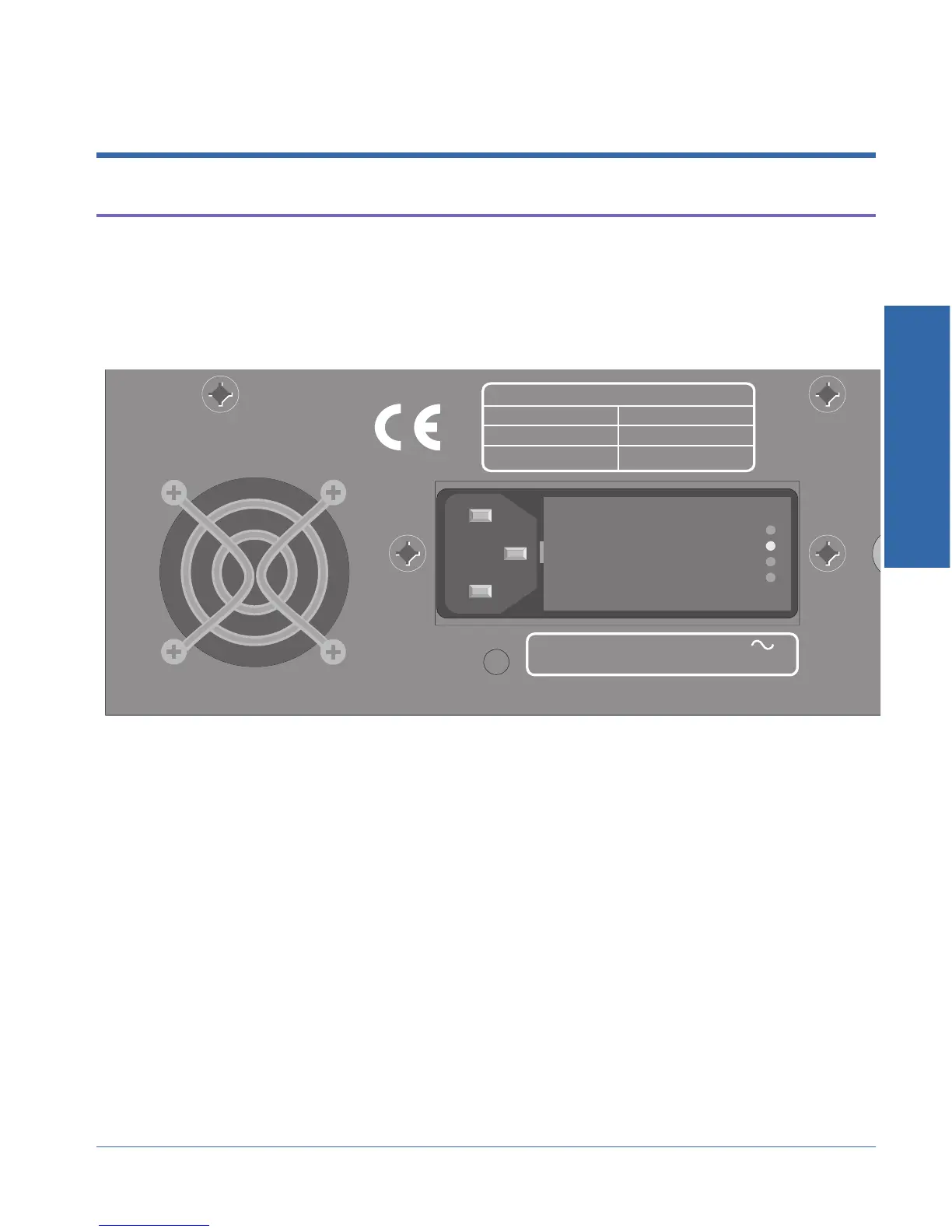
The supply voltage indicator is located on the rear panel of the
instrument next to the power plug (see Figure 2-1). A small white
plastic indicator tip in one of the holes indicates which line voltage is
currently selected.
If the selected voltage is not the same as your local line voltage, see
Appendix A for changing the line voltage selection.
After verifying or correcting the line voltage selection, connect the line
cord from the power outlet to the power cord connector and move the
front-panel Power switch to the ‘On’ position (marked ‘1’).
250mA T/SB 250V
500mA T/SB 250V
FREQUENCY: 50/60 Hz MAXIMUM POWER: 60 VA
SUPPLY VOLTAGE: 100/120/230/240 VAC
FUSE REPLACEMENT DATA
230/240 VAC
100/120 VAC
SUPPLY VOLTAGE FUSE
100 V
120 V
230 V
240 V
Figure 2-1. Location of voltage indicators on rear panel
2 Getting Started
ATS-1 Access User's Manual 2-1