Option Filter Installation
If your ATS-1 was ordered with optional filters, they will have been
installed in the FILTER 1 or FILTER 2 sockets at the factory and
documentation has been provided with the instrument to indicate what
filter is in which socket. If you purchase option filters later to install
yourself, the installation process is as follows:
1. Remove the top cover (only) as described earlier.
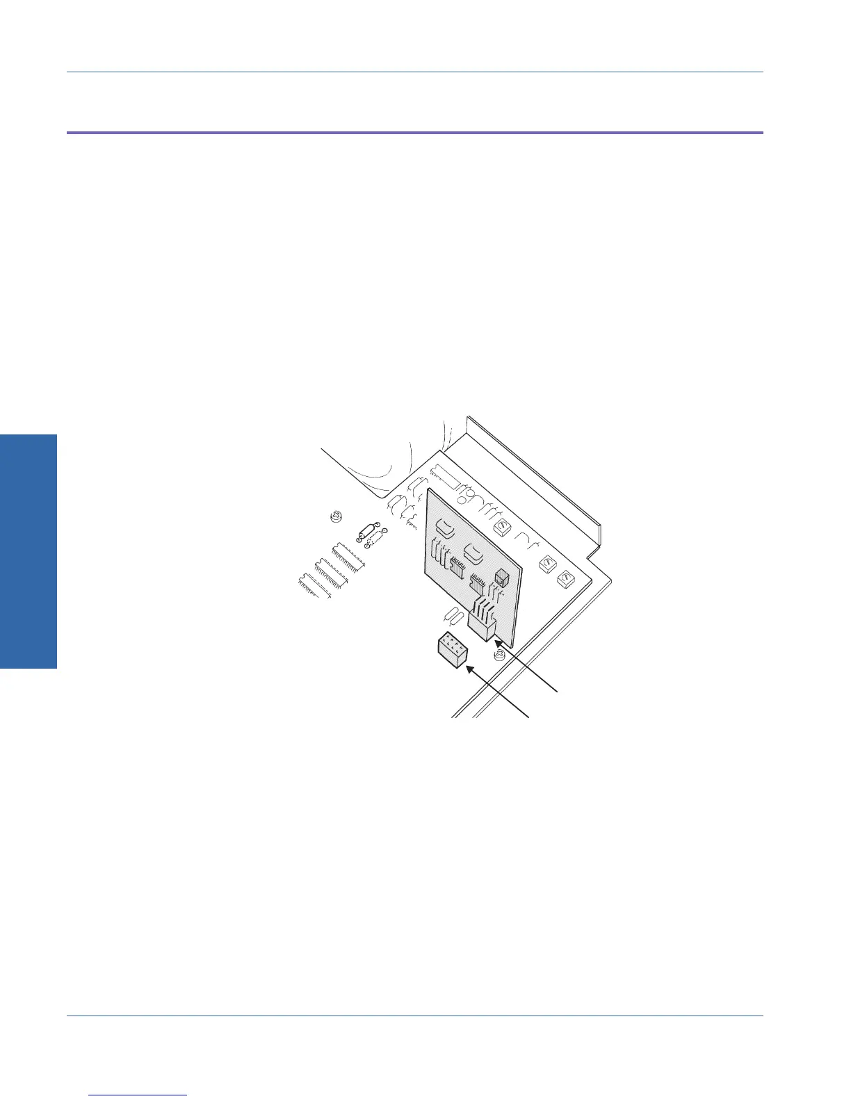
2. The two sockets for option filters are located near the right rear of
the main analyzer circuit board. They are clearly labeled
FILTER 1 and FILTER 2 on the circuit board. Remove the two
screws which secure the filter hold-down bracket, and remove
the hold-down bracket. See Figure C-2.
3. Plug the filter(s) into the desired socket(s), then replace the filter
hold-down bracket and fasten it with the two screws.
4. Replace the top cover.
5. Reconnect power to the unit and turn it on. Select AMPLITUDE
function, INPUT A GEN, and use PANELS mode with analyzer
setup parameters displayed to select the newly-installed filter(s).
Verify their correct function by measuring their frequency
response.
Option Filter
Socket 2 (AUX2)
Option Filter
Socket 1 (AUX1)
REAR OF UNIT
RIGHT SIDE
Figure C-2. Location and orientation of option filters
C Internal Changes
Appendix C - Performing Internal Changes Option Filter Installation
C-6 ATS-1 Access User's Manual