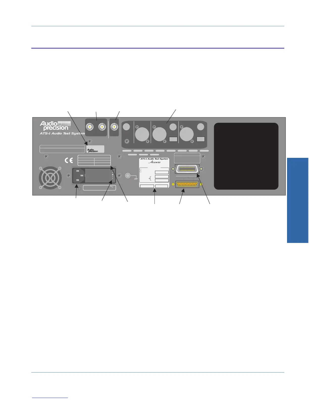
Rear Panel Connectors
Figure shows an overview of the rear panel. The following sections
describe each connector. You will notice provision for additional
connectors that are not installed. This is because the rear panel is
common to both the ATS-1 Access and ATS-1 Dual Domain
instruments, in order to facilitate the upgrade path.
Trigger Output
There is one trigger output provided on the rear panel of the ATS-1
Access, marked ANALOG.
The analog trigger output provides a constant amplitude 1.0 Volt RMS
sinewave that is synchronized to the analog generator output signal. In
IMD generator mode, the signal is synchronous with the lower-
frequency tone.
The analog trigger output is intended primarily to provide a stable
trigger for oscilloscope displays of the monitor signals. The source
impedance for this signal is 680 Ω.
ANALYZER
5Vpp MAX
OPTICAL
BALBAL
DIGITAL OUTPUT
INPUT
REFERENCE
TRIGGER SIGNALS
INPUT ANALOG DIGITAL
UNBAL UNBAL
5Vpp MAX
OPTICAL
MONITORS
DIGITAL INPUT
IEEE-488 INTERFACE
RL1, PP0, DC1, DT1, C0, E1
SH1, AH1, T6, TE0, L4, LE0, SR1,
250mA T/SB 250V
500mA T/SB 250V
FREQUENCY: 50/60 Hz MAXIMUM POWER: 60 VA
SUPPLY VOLTAGE: 100/120/230/240 VAC
FUSE REPLACEMENT DATA
230/240 VAC
100/120 VAC
SUPPLY VOLTAGE FUSE
INSTRUMENT RESET
To restore factory default instrument settings,
hold dBr button and turn on mains power switch.
4,614,914; 4,563,652; 4,631,522; 5,089,981; 5,136,267; 5,265,201;
5,247,458; 5,420,516; 5,336,989.
Other patent applications pending.
This product is protected under one or more of the following patents:
Manufactured in Beaverton, Oregon, USA
GPIB ADDRESS
To set instrument GPIB address,
use utility menu under PANELS
selection on front panel.
R
ATS1-XXXXX
UNBAL
OPTICAL
100 V
120 V
230 V
240 V
OPTIONS
LABEL
GPIB
CONNECTOR
(SPEAKER PANEL)
PRINTER
CONNECTOR
SERIAL NUMBER
LABEL
MONITOR
OUTPUTS
TRIGGER
OUTPUT
DIGITAL
EXPANSION
AREA
FUSE
REPLACEMENT
DATA
POWER
CORD
CONNECTOR
LINE
VOLTAGE
INDICATOR
HOLES
Date of manufacture FW Version
Audio Measurement System
Aux 2:
Aux 1:
Optional Filters:
Installed Options:
Special
EGZ Euro. Impedances
ATS-IMD Intermod. Distortion
Figure 3-12. Rear panel overview
3 Operation
Operational Overview Rear Panel Connectors
ATS-1 Access User's Manual 3-25