4. Slide the selector card back into the housing, with the printed side
of the card facing to the left and the selector pin pointing
outward.
5. Be sure to check the fuse ratings and fuse block orientation before
connecting power to the unit.
Checking the Fuse Block Orientation
Attached to the rear of the Cover (shown on Figure A-2) is the fuse
block. The fuse block can have two orientations. One orientation is
for the 100 V and 120 V settings, and the other is for the 230 V and
240 V settings.
You can tell which arrangement is selected by looking at the back of
the Cover. If you see two fuses, the fuse block is in the 230/240 V
orientation. If you see only one fuse, and a metal jumper bar, the fuse
block is in the 100/120 V orientation. These orientations are shown on
Figure A-5 (page A-5).
If the fuse block is in the correct orientation for the selected voltage,
skip forward to the section on Checking the Fuses (page A-5). If not,
continue with the next section, ‘Changing the Fuse Block Orientation.’
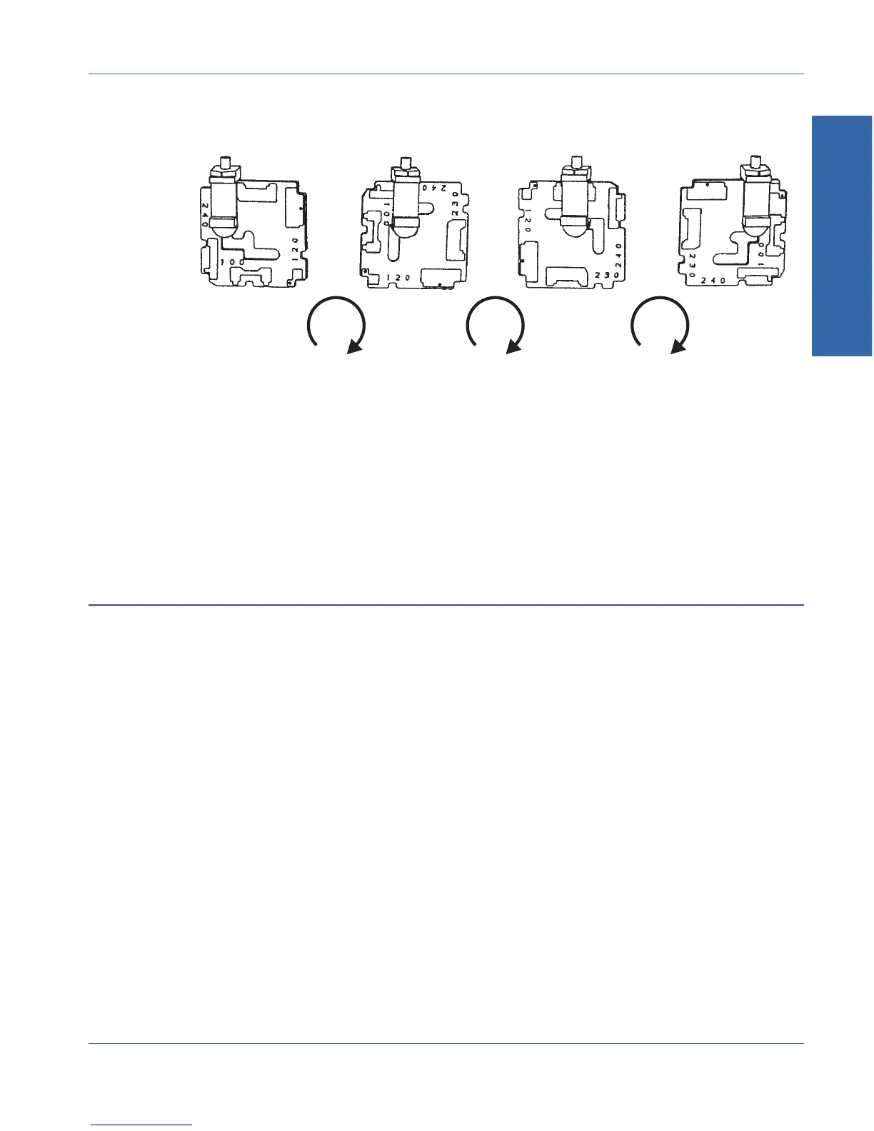
100V 120V 230V 240V
90° 90° 90°
Voltage Selector Card Orientations
Figure A-3. Proper Orientations for Selector Card
A Line and Fuses
Appendix A - Changing Mains Voltage Selection Checking the Fuse Block Orientation
ATS-1 Access User's Manual A-3