5. Remove the four #6-32 nuts which secure the connector panel to
the chassis, and remove the old panel.
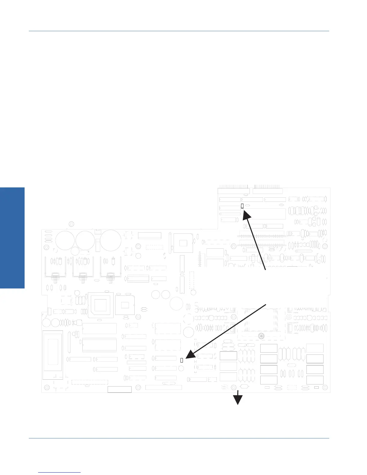
6. Disconnect the cable from the loudspeaker to the circuit board
connector on the bottom side of the chassis at the rear edge of
the circuit board (Location A in Figure C-1).
7. Remove the four #6-32 nuts which secure the loudspeaker panel
to the chassis, and remove the loudspeaker panel.
8. Mount the loudspeaker panel to the front panel with four #6-32
nuts.
9. Connect the loudspeaker cable to the alternative two-pin circuit
board connector on the bottom side of the chassis at the front
edge of the circuit board (Location B in Figure C-1). The
connector polarity is unimportant.
+
+
-
+
+
+ +
+
+
+
precision
Audio
+
+
Alternate speaker connectors
(Generator circuit board
as viewed from bottom
of instrument)
Front of instrument
Location B
Location A
Figure C-1. Alternate Monitor speaker connector locations
C Internal Changes
Appendix C - Performing Internal Changes Swapping Speaker and Connector Panels
C-4 ATS-1 Access User's Manual