EasyManuals Logo

Audio Precision ATS-1 Access User Manual

Audio Precision ATS-1 Access
161 pages
To Next Page IconTo Next Page
To Previous Page IconTo Previous Page
Page #146 background imageLoading...
Page #146 background image
1. Remove the top cover (only) as described earlier in this section.
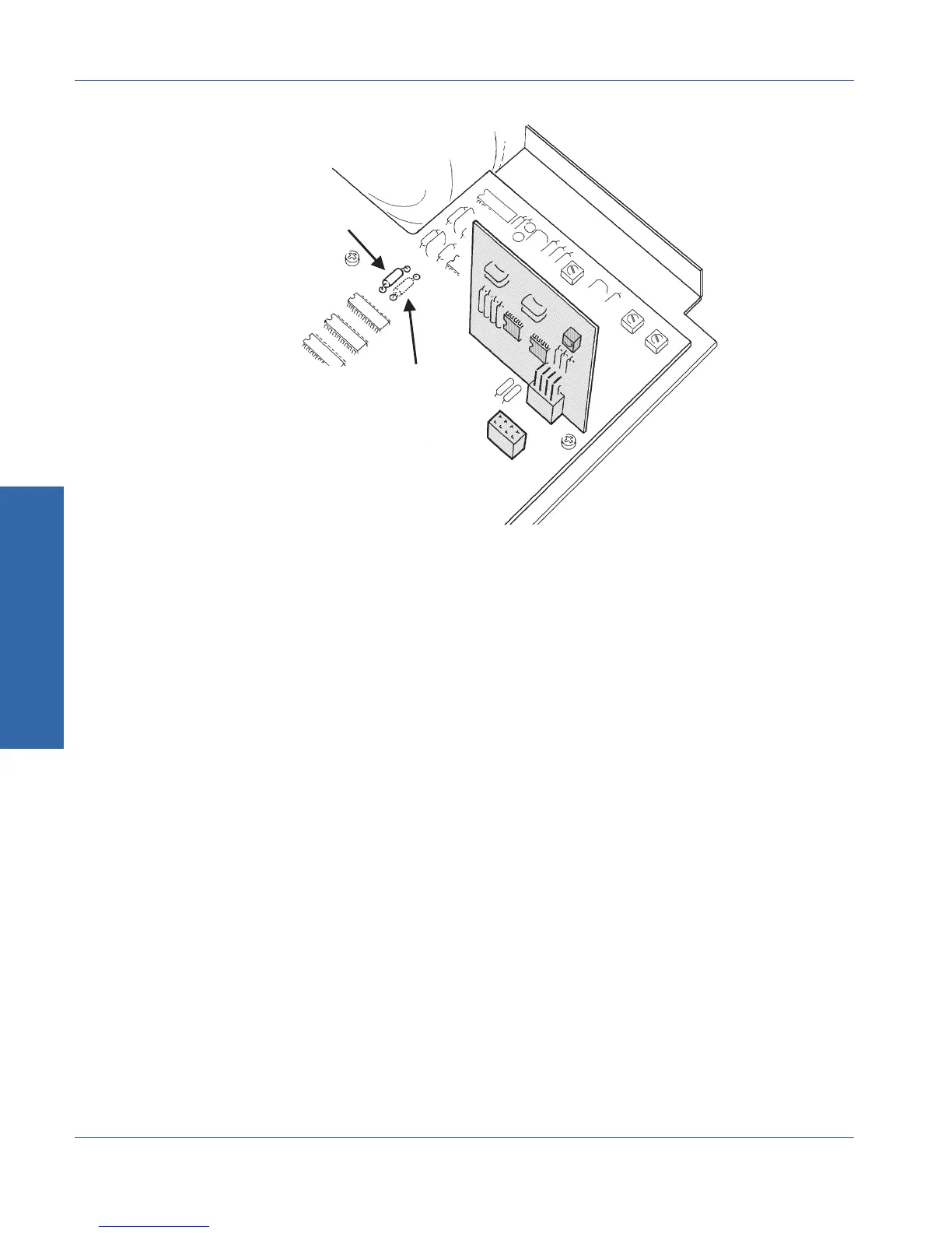
2. Locate resistor R2501, 620 , at the location on the Analyzer
circuit board as shown on Figure C-3 above.
3. Move this resistor to its alternate location (R2502). With the
resistor in this position, the monitor signal will come from the
final processed reading.
4. Replace the top cover.
R2501
R2502
REAR OF UNIT
RIGHT SIDE
Figure C-3. Cable positions for monitor selection
C Internal Changes
Appendix C - Performing Internal Changes Monitor Source Selection
C-8 ATS-1 Access User's Manual

Table of Contents

Questions and Answers:

Question and Answer IconNeed help?

Do you have a question about the Audio Precision ATS-1 Access and is the answer not in the manual?

Audio Precision ATS-1 Access Specifications

General IconGeneral
BrandAudio Precision
ModelATS-1 Access
CategoryTest Equipment
LanguageEnglish

Related product manuals