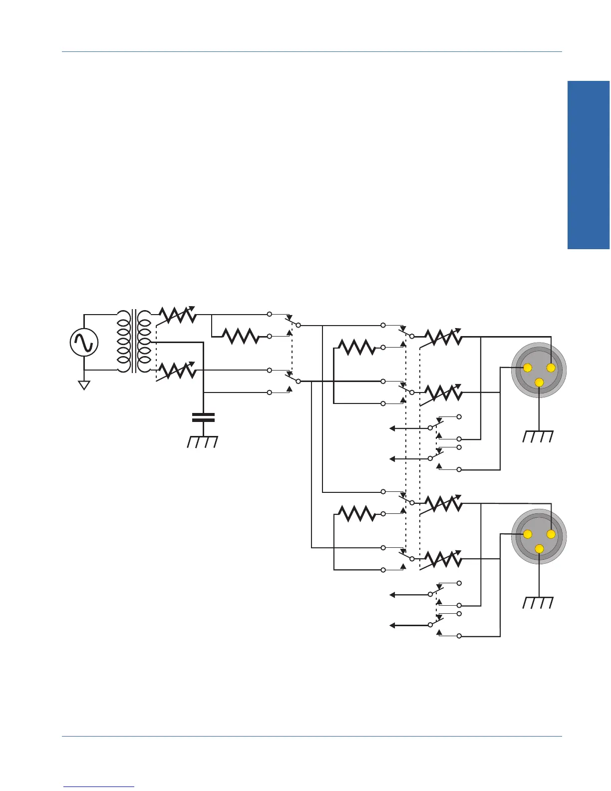
When the generator output is turned off, a floating 50 Ω resistor is
connected in place of the generator to back-terminate the output
connector so that proper noise measurements can be made.
Output impedance selection is made by switching buildout resistors at
the output connector.
When generator monitor inputs are used, the connection (labeled GEN
MON in the diagram) is made directly across the output connector
terminals.
Note that the power amplifier, output transformer, and output
attenuator are common to both channels.
CT
25 Ω
50 Ω
50 Ω
Circuit comon
Chassis
Output
Attenuator
On/Off
15 nF
typical
Balanced/
Unbalanced
To Analyzer
GEN A MON
To Analyzer
GEN B MON
Source
Impedance
Output A
Output B
Figure 1-7. Simplified generator output circuit
1 Description
Description Generator Output Circuit
ATS-1 Access User's Manual 1-13