USER’S MANUAL / bit Tune /
70
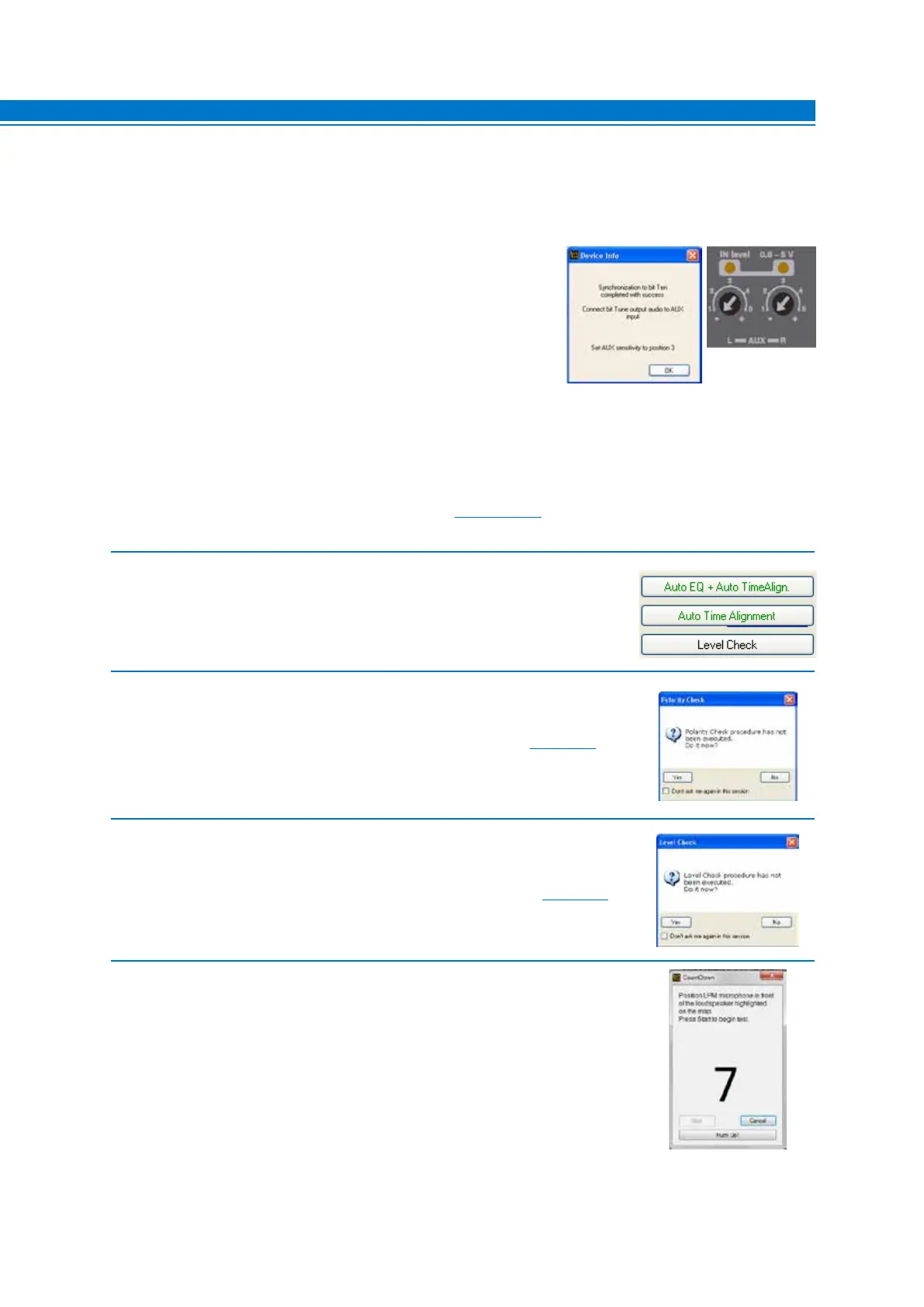
2. - Choose Auto Time Alignment from the main menu of the PC Software,
if you want to perform the automatic calibration of the system’s time delays.
3. The system will ask if you want to perform a phase measurement of the system’s
speakers (Polarity Check) via the LPM microphone, placed near the speakers.
- Choose YES to perform a phase measurement of the speakers (see sect. 7.3).
- Choose NO to skip this operation if it was already performed earlier.
- Choose Don’t ask me again, to cancel the request for future measurements.
4. The system will ask if you want to measure the levels of the system’s speakers
(Level Check) via the LPM microphone positioned as shown in fig. 1,2.
- Choose YES to perform the measurement of the speakers’ levels (see sect. 7.5)
- Choose NO to skip this operation if it was already performed earlier.
- Choose Don’t ask me again, to cancel the request for future measurements.
5. Place the HSM microphone in the fastening bracket on the headrest corresponding
to the listening point chosen on the system’s Channel Map.
- Select one of the available processor memories for saving the measurement settings.
- Click Start to start the measurement. This may take several minutes.
- Click Cancel to quit the measurement.
7
1. Connect the bit Tune to the Audison bit processor, as shown in fig. 1, 2 or 3 (see points A, B and C).
The AUTO TIME ALIGNMENT procedure must be performed in an environment that is not noisy,
with the car’s engine off, air conditioning off, doors and windows tightly closed and radio frequency
devices away from the car’s passenger compartment.
- Turn the bit Tune on and connect the USB cable to the PC.
- Set the function switch of the bit Tune on PC ANALYZER.
- Turn on the Audison bit processor and connect the USB cable to
the bit Tune.
- Start the bit Tune software by clicking the icon on the PC desktop
and launch the software in bit Tune + Processor mode.
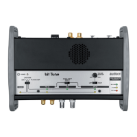
A. bit Ten: Connect the AUX Left and Right inputs of the bit Ten to
the Pre Out Left and Right outputs of the bit Tune, and set the
level of the AUX inputs to position 1.
B. bit One: Connect the AUX1 Left and Right inputs of the bit One to the Pre Out Left and Right outputs
of the bit Tune.
C. AP bit: connect the Aux input to the L-R outputs of the bit Tune, ensuring that the AUX input is enabled. If
you want to connect the bit Tune to AP bit amplifiers to perform measurements, but the AUX input port is
already occupied, you can use the OPTICAL input (see section 4.5.6).