4. Assembly
4.1. Mounting position
The product described in this document can be operated in any mounting position.
Restriction: When using oil instead of grease within the actuator gear housing, the
hollow shaft mounting position must be perpendicular, with the flange pointing
downward.The type of lubricant used is indicated on the actuator name plate (short
designation F...= grease; O...= oil).
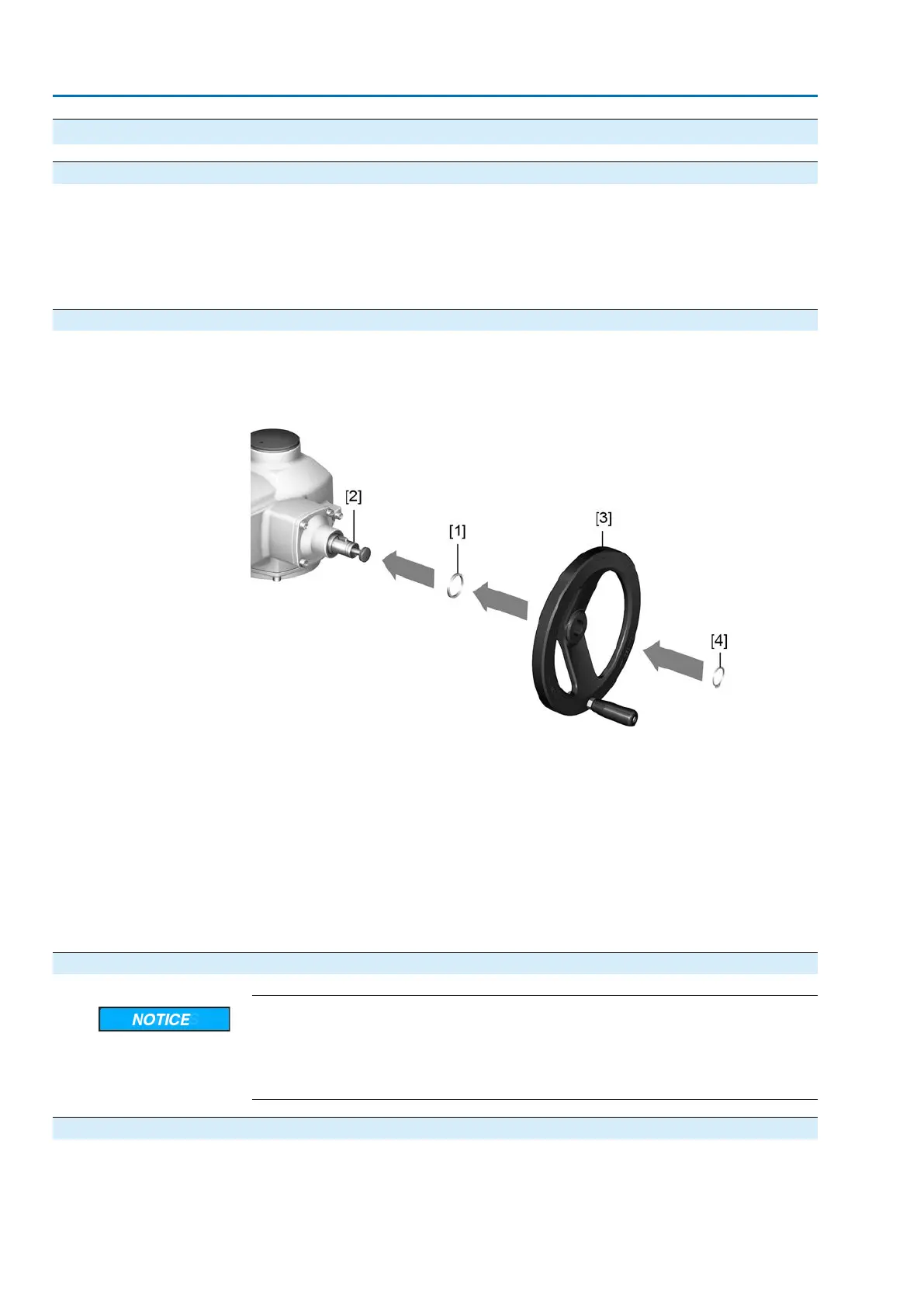
4.2. Handwheel fitting
Information For transport reason, handwheels with a diameter of 400 mm and larger are supplied
separately within the scope of delivery.
Figure 8: Handwheel
[1] Spacer
[2] Input shaft
[3] Handwheel
[4] Retaining ring
1. If required, fit spacer [1] on input shaft [2].
2. Slip handwheel [3] onto input shaft.
3. Secure handwheel [3] using the retaining ring [4] supplied.
Information
The retaining ring [4] (together with these operation instructions) is stored in a
weatherproof bag, which is attached to the device prior to delivery.
4.3. Multi-turn actuator: mount to valve/gearbox
Danger of corrosion due to damage to paint finish and condensation!
→
Touch up damage to paint finish after work on the device.
→
After mounting, connect the device immediately to electrical mains to ensure
that heater minimises condensation.
4.3.1. Output drive type A
Application
●
Output drive for rising, non-rotating valve stem
●
Capable of withstanding thrust
16
SA 07.2 – SA 16.2 /SAR 07.2 – SAR 16.2
Assembly AM 01.1/AM 02.1

 Loading...


