9.6.4. PTC tripping device (option): test
1. Turn selector switch to position Test (spring return).
➥
If the PTC tripping device is working properly, the tripping of the motor protection
is signalled via the red "collective fault signal" indication light on the local con-
trols.
2. Turn selector switch to position Reset.
➥
The fault signal is reset if the device is working properly.
3. If no fault signal is initiated: Request AUMA Service for inspection of actuator
controls
9.7. Switch compartment: close
✔
If options (e.g. potentiometer, position transmitter) are available: Only close switch
compartment once all optional equipment has been successfully set.
Danger of corrosion due to damage to paint finish!
→
Touch up damage to paint finish after work on the device.
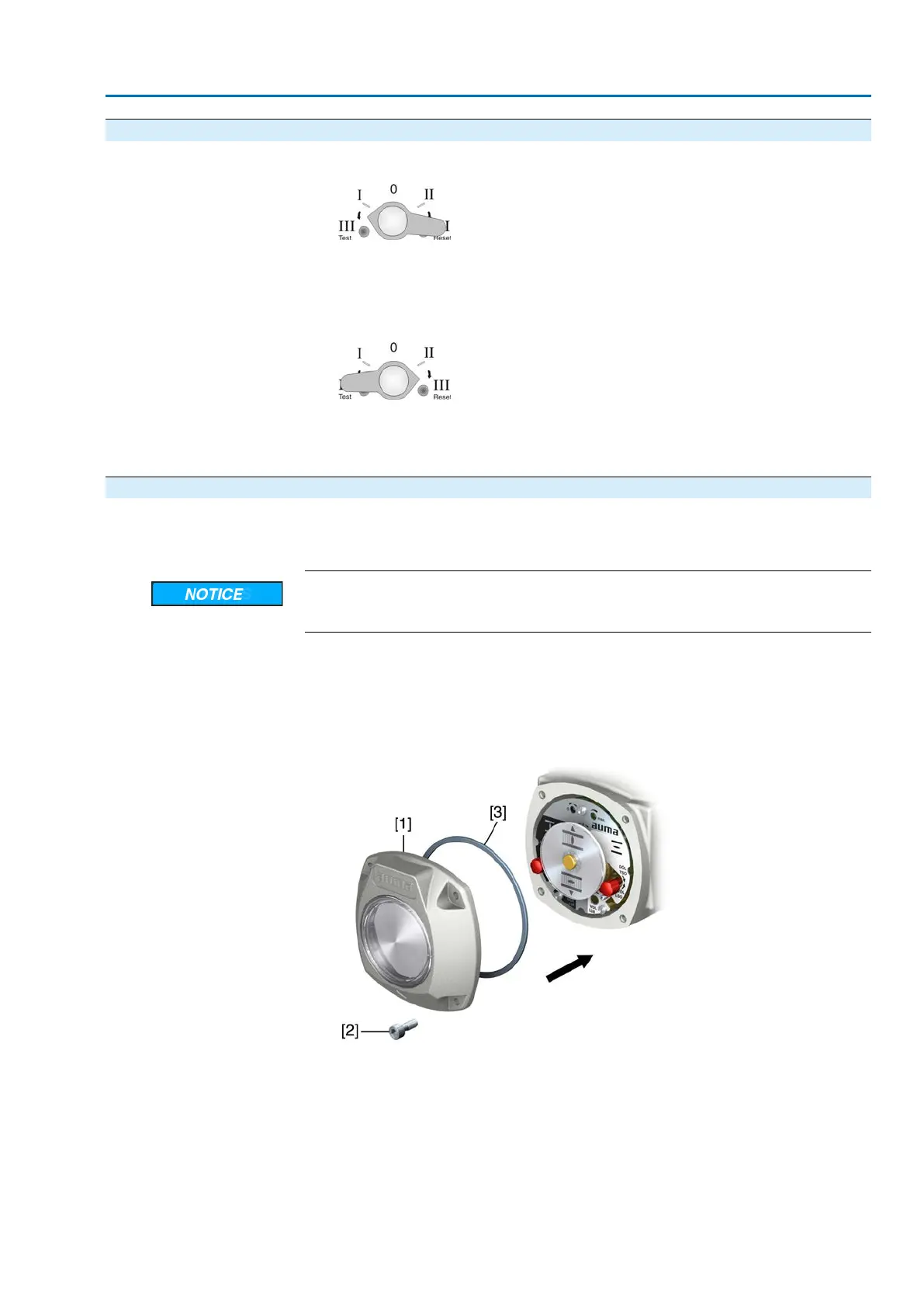
1. Clean sealing faces of housing and cover.
2. Check whether O-ring [3] is in good condition, replace if damaged.
3. Apply a thin film of non-acidic grease (e.g. petroleum jelly) to the O-ring and
insert it correctly.
Figure 37:
4. Place cover [1] on switch compartment.
5. Fasten screws [2] evenly crosswise.
45
SA 07.2 – SA 16.2 /SAR 07.2 – SAR 16.2
AM 01.1/AM 02.1 Commissioning (basic settings)

 Loading...


