2. Screw stem protection tube [2] into thread and tighten it firmly.
Information: For stem protection tubes made of two or more segments, all
parts have to be thoroughly screwed together.
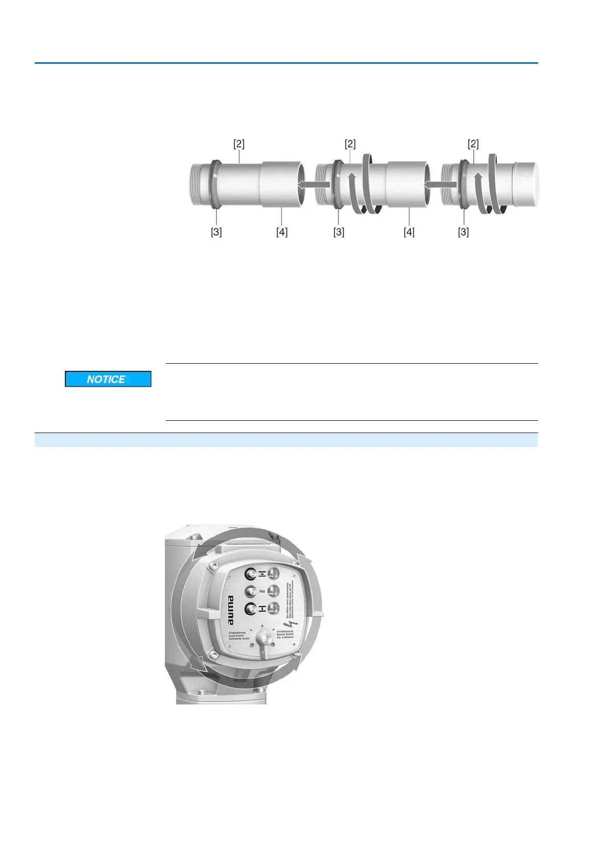
Figure 15: Protection tube made of segments with threaded sleeves (>900 mm)
[2] Segment of stem protection tube
[3] V-seal
[4] Threaded sleeve
3. Push down the sealing ring [3] onto the housing.
Information: For mounting segments, push down seals of segments down to
the sleeve (connecting piece).
4. Check whether protective cap [1] for stem protection tube is available, in perfect
condition and tightly placed on or screwed to the tube.
Risk of bending or oscillation of protection tubes exceeding a length of 2 m!
Risk of damage at stem and/or protection tube.
→
Secure protection tubes exceeding 2 m by an appropriate support.
4.6. Mounting positions of local controls
The mounting position of the local controls is designed according to the order. If,
after mounting the actuator to the valve or the gearbox on site, the local controls are
in an unfavourable position, the mounting position can be changed at a later date.
Four mounting positions shifted by respectively 90° are possible.
Figure 16: Mounting positions
22
SA 07.2 – SA 16.2 /SAR 07.2 – SAR 16.2
Assembly AM 01.1/AM 02.1

 Loading...


