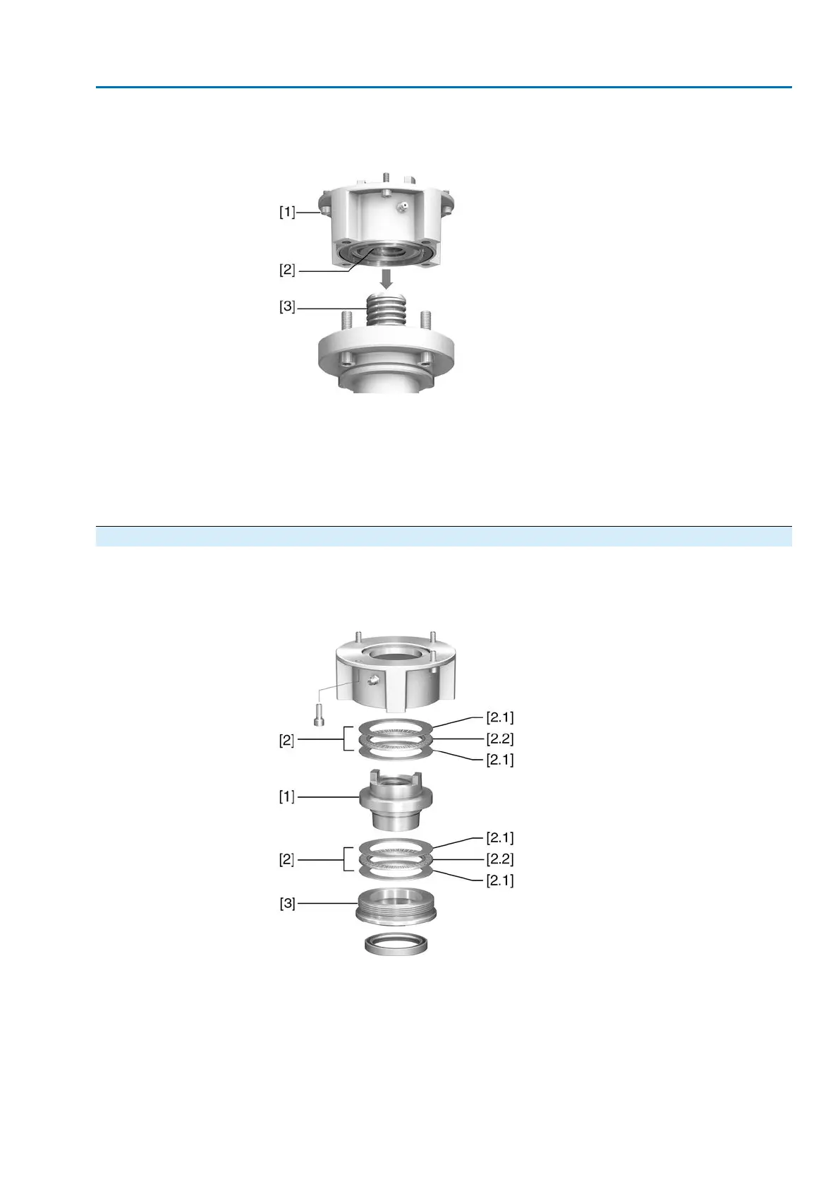
Design
Output mounting flange [1] with axial bearing stem nut [2] form one unit.Torque is
transmitted to valve stem [3] via stem nut [2].
Figure 9: Design of output drive type A
[1] Output mounting flange
[2] Stem nut with dog coupling
[3] Valve stem
Information
To adapt the actuators to available output drive types A with flanges F10 and F14
(year of manufacture: 2009 and earlier), an adapter is required.The adapter can be
ordered from AUMA.
4.3.1.1. Stem nut: finish machining
✔
This working step is only required if stem nut is supplied unbored or with pilot
bore.
Figure 10: Output drive type A
[1] Stem nut
[2] Axial needle roller bearing
[2.1] Axial bearing washer
[2.2] Axial needle roller and cage assembly
[3] Spigot ring
1. Remove spigot ring [3] from output drive.
2. Remove stem nut [1] together with axial needle roller bearings [2].
17
SA 07.2 – SA 16.2 /SAR 07.2 – SAR 16.2
AM 01.1/AM 02.1 Assembly

 Loading...


