3. Press down and turn setting spindle [4] with screw driver in direction of the
arrow and observe the pointer [5]: While a ratchet click is felt and heard, the
pointer [5] moves 90° every time.
4. As soon as the pointer [5] is 90° from mark [6]: Continue turning slowly.
5. As soon as the pointer [5] moves to mark [6]: Stop turning and release setting
spindle.
➥
The intermediate position setting in running direction OPEN is complete.
6. If you override the tripping point inadvertently (ratchet click is heard after the
pointer has snapped): Continue turning the setting spindle in the same direction
and repeat setting process.
9.6. Test run
Only perform test run only once all settings previously described have been
performed.
9.6.1. Direction of rotation at mechanical position indicator: check
Valve damage due to incorrect direction of rotation!
→
If the direction of rotation is wrong, switch off immediately (press STOP).
→
Eliminate cause, i.e. correct phase sequence for cable set wall bracket.
→
Repeat test run.
Information Switch off before reaching the end position.
1. Move actuator manually to intermediate position or to sufficient distance from
end position.
2. Switch on actuator in direction CLOSE and observe the direction of rotation on
the mechanical position indication:
→
For mechanical position indication via indicator mark: (not self-adjust-
ing)
➥
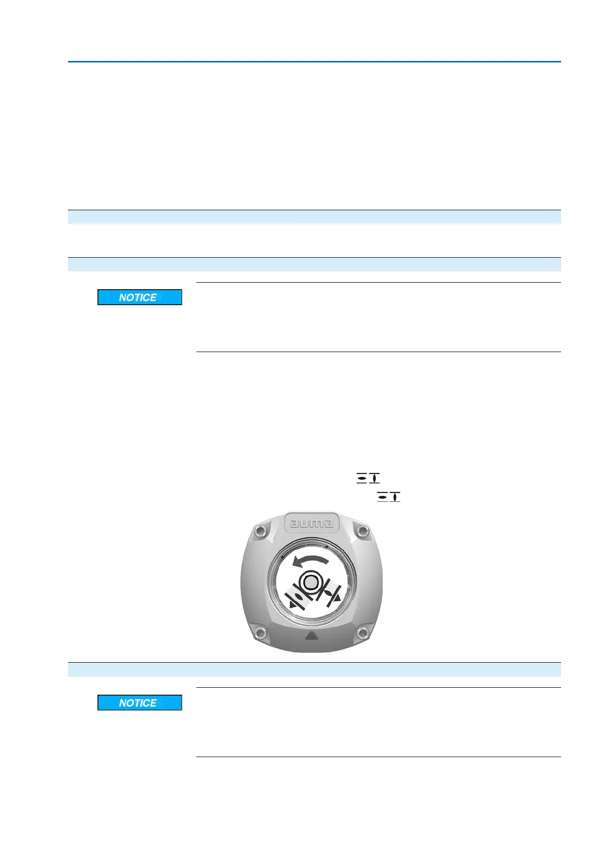
The direction of rotation is correct if the actuator operation in direction
CLOSE and the symbols ( / ) turn counterclockwise:
Figure 35: Direction of rotation / (for “clockwise closing version”)
9.6.2. Direction of rotation at hollow shaft/stem: check
Valve damage due to incorrect direction of rotation!
→
If the direction of rotation is wrong, switch off immediately (press STOP).
→
Eliminate cause, i.e. correct phase sequence for cable set wall bracket.
→
Repeat test run.
Information Switch off before reaching the end position.
43
SA 07.2 – SA 16.2 /SAR 07.2 – SAR 16.2
AM 01.1/AM 02.1 Commissioning (basic settings)

 Loading...


