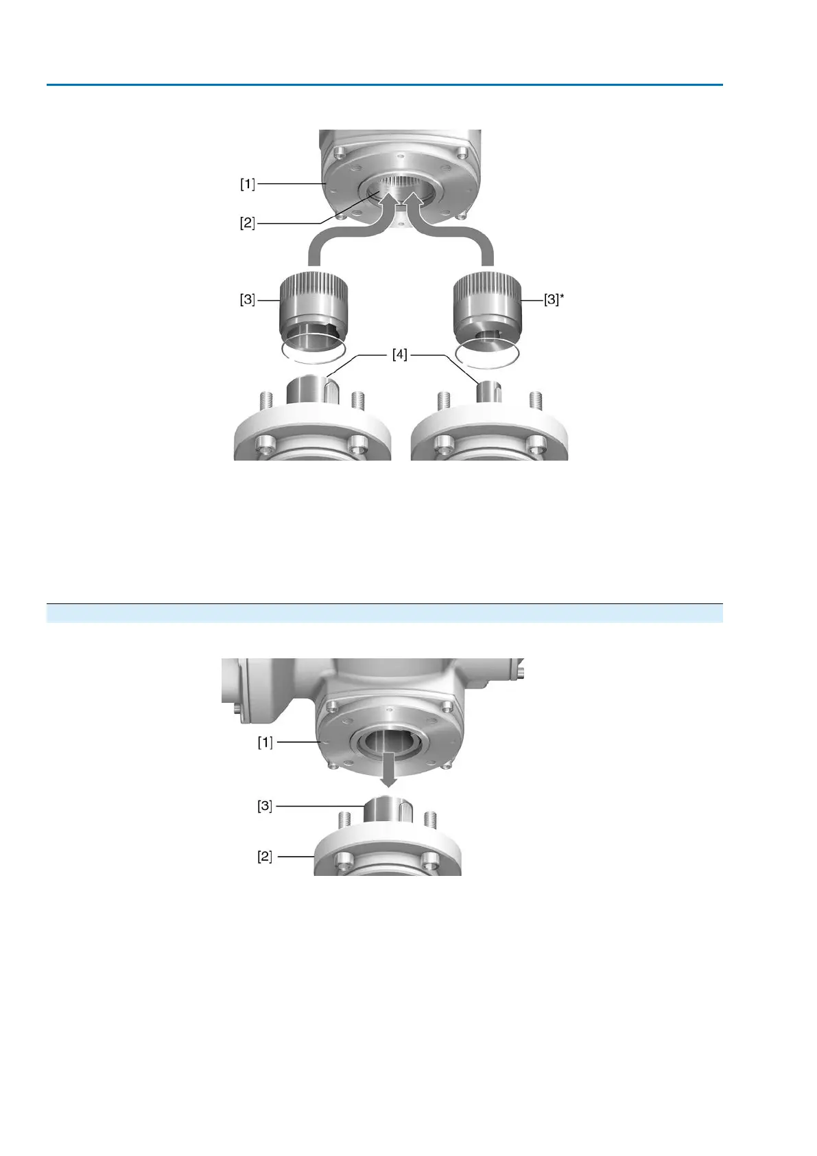
Figure 12: Output drive type B
[1] Flange multi-turn actuator (e.g. F07)
[2] Hollow shaft
[3] Output drive sleeve (illustration examples)
[3] B/B1/B2 and [3]* B3/B4/E, respectively with bore and keyway
[4] Gearbox/valve shaft with parallel key
Information
Spigot at valve flanges should be loose fit.
4.4.1. Multi-turn actuator with output drive types B: mount to valve/gearbox
Figure 13: Mounting output drive types B
[1] Multi-turn actuator
[2] Valve/gearbox
[3] Valve/gearbox shaft
1. Check if mounting flanges fit together.
2. Check if output drive of multi-turn actuator [1] matches the output drive of
valve/gearbox or valve/gearbox valve shaft [2/3].
3. Apply a small quantity of grease to the valve or gearbox shaft [3].
4. Fit multi-turn actuator [1].
Information: Ensure that the spigot fits uniformly in the recess and that the
mounting faces are in complete contact.
20
SA 07.2 – SA 16.2 /SAR 07.2 – SAR 16.2
Assembly AM 01.1/AM 02.1

 Loading...


