2. Turn potentiometer [1] clockwise to the stop.
➥
End position CLOSED corresponds to 0 %
➥
End position OPEN corresponds to 100 %
3. Turn potentiometer [1] slightly in opposite direction.
4. Perform fine-tuning of the zero point at external setting potentiometer (for remote
indication).
10.3. RWG electronic position transmitter
The RWG electronic position transmitter records the valve position. On the basis of
the actual position value measured by the potentiometer (travel sensor), it generates
a current signal between 0 – 20 mA or 4 – 20 mA.
Technical data
Table 19: RWG 4020
2-wire system3-wire and 4-wire systemsData
4 – 20 mA0 – 20 mA, 4 – 20 mAOutput current I
a
14 V DC + (I x R
B
), max. 30 V24 V DC (18 – 32 V)Power supply U
V
1)
20 mA24 mA at 20 mA output currentMax. current consumption
(U
V
– 14 V)/20 mA600 ΩMax. load R
B
0.1 %/V0.1 %/VImpact of power supply
0.1 %/100 Ω0.1 %/(0 – 600 Ω)Load influence
< 0.3 ‰/KTemperature impact
–60 °C to +80 °CAmbient temperature
2)
5 kΩTransmitter potentiometer
Power supply possible via: AC, AM actuator controls or external power supply1)
Depending on temperature range of the actuator: Refer to name plate2)
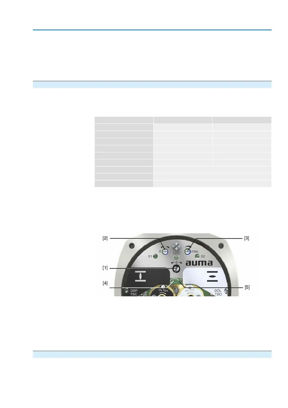
Setting elements
The RWG is housed in the actuator switch compartment. The switch compartment
must be opened to perform any settings. Refer to <Switch compartment: open>.
Setting is made via three potentiometers [1], [2] and [3].
Figure 40: View on control unit when switch compartment is open
[1] Potentiometer (travel sensor)
[2] Potentiometer min. (0/4 mA)
[3] Potentiometer max. (20 mA)
[4] Measuring point (+) 0/4 – 20 mA
[5] Measuring point (–) 0/4 – 20 mA
The output current (measuring range 0 – 20 mA) can be checked at measuring points
[4] and [5].
10.3.1. Measuring range: set
For measuring range setting, voltage must be applied at the position transmitter.
1. Move valve to end position CLOSED.
49
SA 07.2 – SA 16.2 /SAR 07.2 – SAR 16.2
AM 01.1/AM 02.1 Commissioning (optional equipment settings)

 Loading...


