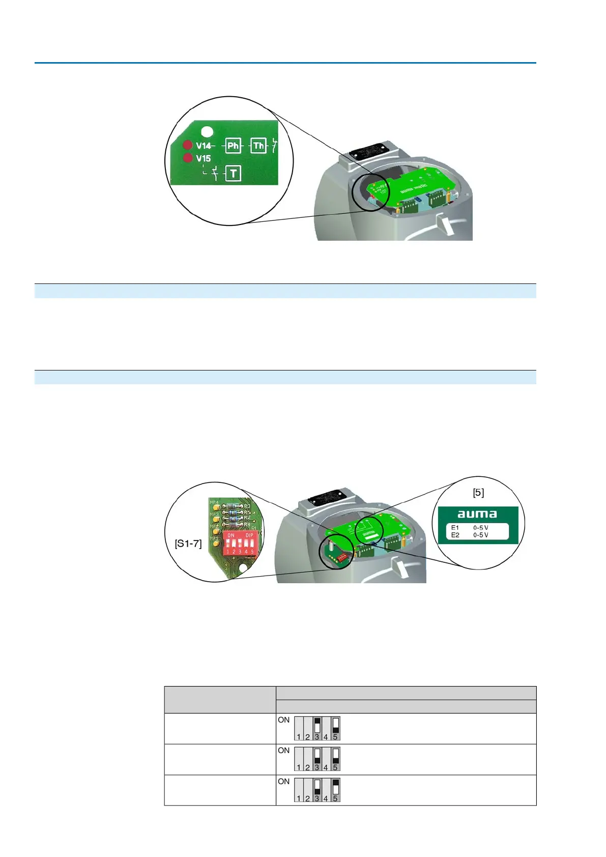
Figure 45: LEDs on interface board
[V14] illuminated: Phase failure (Ph) and/or motor protection (Th) tripped
[V15] illuminated: Torque fault (T), tripping torque reached in mid-travel.
11.7. Positioner
— (Option) —
→
Prior to positioner setting, set limit and torque switching as well as potentiometer
or electronic position transmitter.
11.7.1. Input ranges (signal type) for setpoint and actual value
The input range (signal type) for setpoint E1 and actual value E2 is set in the factory
and marked with a label on the cover plate of the positioner.
The type of signal can be modified at a later date exclusively for versions with setpoint
E1 ≠ 0/4 – 20 mA and split-range version. For these versions, the positioner board
is equipped with an additional contact.
Figure 46: Version with additional switch on the positioner board
[5] Label indicating the set input ranges
[S1-7]5-contact DIP switch for setting
DIP1 Actual value E2 (current or voltage signal)
DIP3 Setpoint E1 (current or voltage signal)
DIP5 Setpoint E1 (double signal range e.g. for split range)
Table 20: Input range setting for setpoint E1
[S1–7]Setpoint E1
DIP 3 and 5
0/4 – 20 mA
0 – 5 V
0 – 10 V
54
SA 07.2 – SA 16.2 /SAR 07.2 – SAR 16.2
Commissioning – controls settings AM 01.1/AM 02.1

 Loading...


