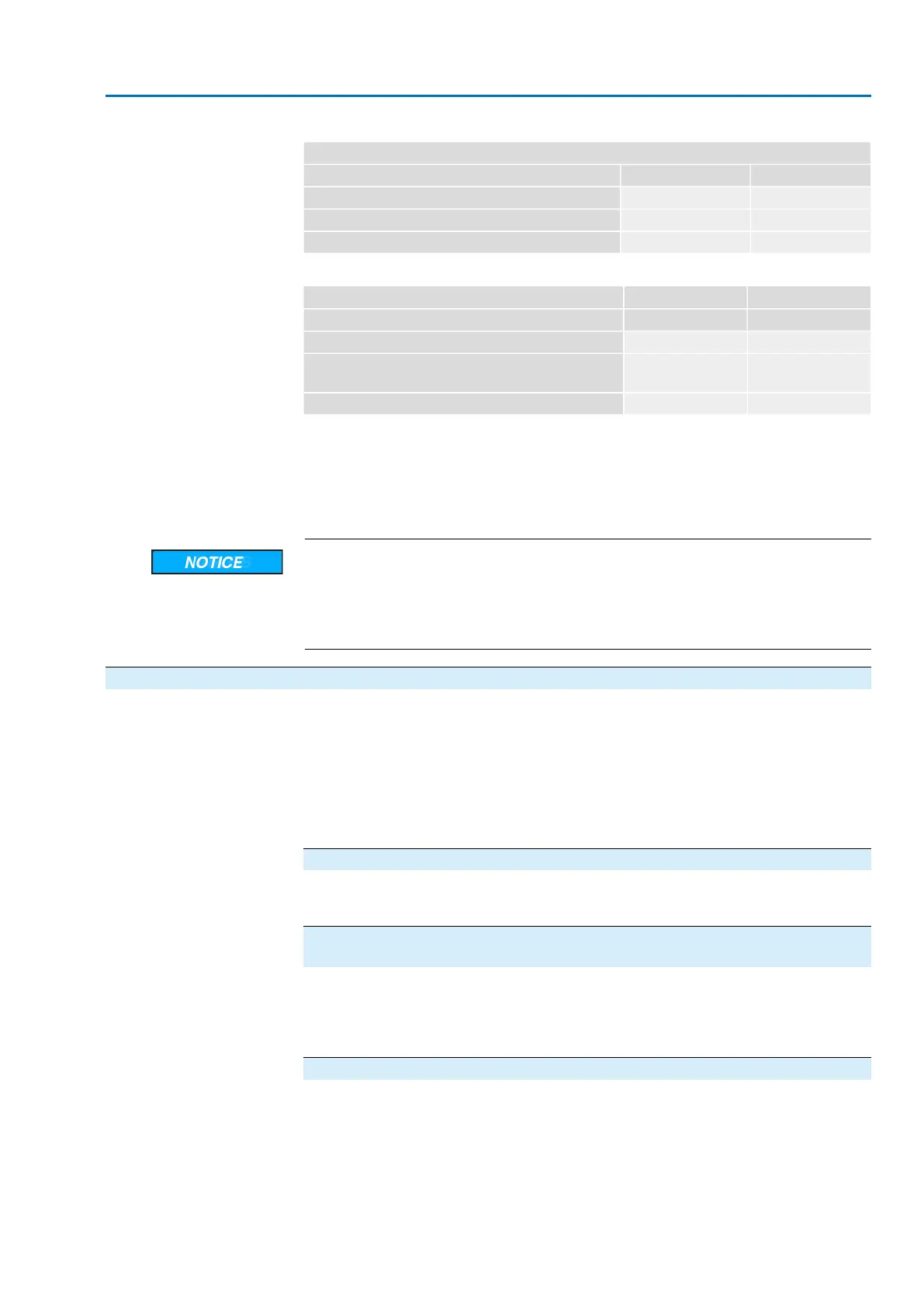
Table 26:
Secondary fuse F3 (internal 24 V DC supply)
AUMA Art.no.:F3G fuse according to IEC 60127-2/III
5 x 20 mmSize
K001.183500 mA T; 250 VVoltage output (power supply unit) = 24 V
K001.183500 mA T; 250 VVoltage output (power supply unit) = 115 V
Table 27:
Secondary fuse F4 (internal AC supply)
1)
AUMA Art.no.:F4G fuse according to IEC 60127-2/III
5 x 20 mmSize
K004.831
K003.131
1.0 A T; 250 V
1.6 A T; 250 V
Voltage output (power supply unit) = 24 V
K003.0210.4 A T; 250 VVoltage output (power supply unit) = 115 V
Fuse for: switch compartment heater, reversing contactor control, PTC tripping device (at 24 V AC
only), at 115 V AC also control inputs OPEN, STOP, CLOSE
1)
Information
Only replace fuses with fuses of the same type and value.
→ After replacing the fuses, tighten local controls again.
Cable damage due to twisting or pinching!
Risk of functional failures.
→
Turn local controls by a maximum of 180°.
→
Carefully assemble local controls to avoid pinching the cables.
12.2.2. Motor protection (thermal monitoring)
In order to protect against overheating and impermissibly high surface temperatures
at the actuator, PTC thermistors or thermoswitches are embedded in the motor
winding.The thermoswitch is tripped as soon as the max. permissible winding
temperature has been reached.
The actuator is stopped and the "collective fault" indication light (option) on the local
controls is illuminated.
The motor has to cool down before the operation can be resumed.
Version with thermoswitch (standard)
The actuator can be controlled again once the motor has cooled down ("collective
fault" indication light goes out).
Version with thermoswitch and additional thermal overload relay in actuator
controls (option)
The operation may only be resumed once the fault signal ("collective fault" indication
light) has been reset.The fault signal is reset via the overload relay integrated in the
actuator controls.Therefore, actuator controls have to be opened at the cover and
the relay held down.The relay is located on the contactors.
Version with PTC thermistor (option)
The operation may only be resumed once the fault signal ("collective fault" indication
light) has been reset.The fault signal is reset via selector switch position Reset of
the local controls.
63
SA 07.2 – SA 16.2 /SAR 07.2 – SAR 16.2
AM 01.1/AM 02.1 Corrective action

 Loading...


