●
Avoid parallel paths with little cable distance of cables being either susceptible
to interference or interference sources.
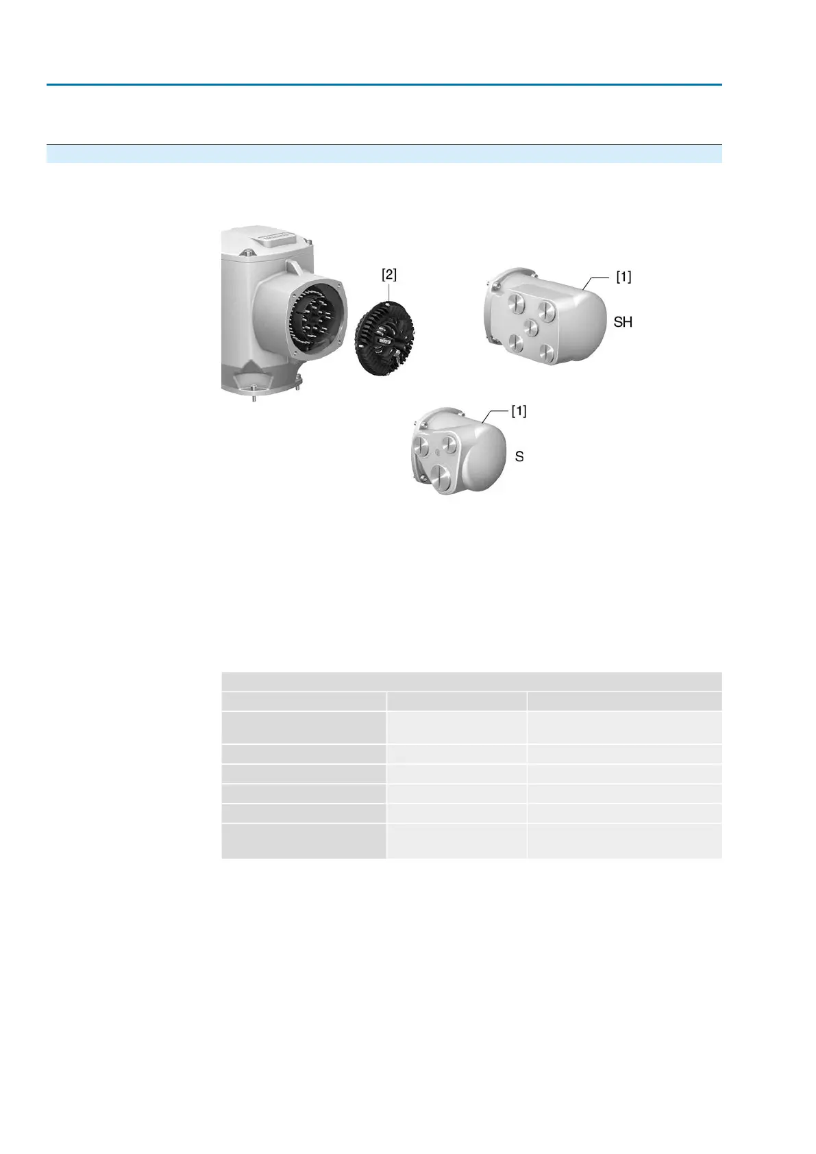
5.2. Electrical connection S/SH (AUMA plug/socket connector)
Figure 18: S and SH electrical connection
[1] Cover
[2] Socket carrier with screw-type terminals
Short description
Plug-in electrical connection with screw-type terminals for power and control contacts.
Control contacts also available as crimp-type connection as an option.
S version (standard) with three cable entries. SH version (enlarged) with additional
cable entries. For cable connection, remove the AUMA plug/socket connector and
the socket carrier from cover.
Technical data
Table 13:
Electrical connection via AUMA plug/socket connector
Control contactsPower contacts
50 pins/sockets6 (3 equipped) + protective
earth conductor (PE)
No. of contacts max.
1 to 50U1, V1, W1, U2, V2, W2, PEDesignation
250 V750 VConnection voltage max.
16 A25 ARated current max.
Screw connection, crimp-type (option)Screw connectionType of customer connection
2.5 mm
2
(flexible or solid)
6 mm
2
(flexible)
10 mm
2
(solid)
Connection diameter max.
Information
For some special motors, the connection of the power terminals (U1, V1, W1, U2,
V2, W2) is not performed via the AUMA plug/socket connector but via a terminal
board directly at the motor.
26
SA 07.2 – SA 16.2 /SAR 07.2 – SAR 16.2
Electrical connection AM 01.1/AM 02.1

 Loading...


