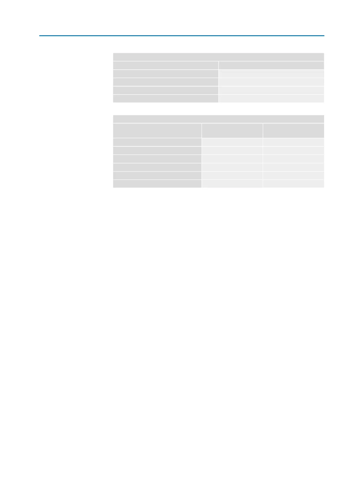
Table 11:
Current consumption controls
Max. current consumptionMains voltage
575 mA100 to 120 V AC (±10 %)
275 mA208 to 240 V AC (±10 %)
160 mA380 to 500 V AC (±10 %)
500 mA24 V DC (+20 %/-15 %) and AC motor
Table 12:
Maximum permissible protection
max. protectionRated powerSwitchgear
(switchgear with power class)
1)
16 A (gL/gG)up to 1.5 kWReversing contactor A1
32 A (gL/gG)up to 7.5 kWReversing contactor A2
63 A (gL/gG)up to 15 kWReversing contactor A3
16 A (g/R) I²t<1,500A²sup to 1.5 kWThyristor B1
32 A (g/R) I²t<1,500A²sup to 3 kWThyristor B2
63 A (g/R) I²t<5,000A²sup to 5.5 kWThyristor B3
The AUMA power class (A1, B1, ...) is indicated on the actuator controls name plate1)
Consider the motor starting current (I
A
) (refer to electrical data sheet) when selecting
the circuit breaker.We recommend tripping characteristics D or K for circuit breakers
in accordance with IEC 60947-2. For controls with thyristors, we recommend safety
fuses instead of circuit breakers.
We recommend refraining from using residual current devices (RCD). However, if
an RCD is used within the mains, the residual current device must be of type B.
If actuator controls are mounted separately from actuator (actuator controls on wall
bracket): Consider length and cross section of connecting cable when defining the
protection required.
Potential of customer
connections
All input signals (control inputs) must be supplied with the same potential.
All output signals (status signals) must be supplied with the same potential.
Safety standards
Safety measures and safety equipment must comply with the respectively valid
national on site specifications. All externally connected devices shall comply with
the relevant safety standards for the place of installation.
Connecting cables
●
We recommend using connecting cables and connecting terminals according
to rated current (I
N
) (refer to motor name plate or electrical data sheet).
●
For device insulation, appropriate (voltage-proof) cables must be used. Specify
cables for the highest occurring rated voltage.
●
Use connecting cable with appropriate minimum rated temperature.
●
For connecting cables exposed to UV radiation (outdoor installation), use UV
resistant cables.
●
For the connection of position transmitters, screened cables must be used.
Cable installation in ac-
cordance with EMC
Signal and fieldbus cables are susceptible to interference. Motor cables are
interference sources.
●
Lay cables being susceptible to interference or sources of interference at the
highest possible distance from each other.
●
The interference immunity of signal and fieldbus cables increases if the cables
are laid close to the earth potential.
●
If possible, avoid laying long cables and make sure that they are installed in
areas being subject to low interference.
25
SA 07.2 – SA 16.2 /SAR 07.2 – SAR 16.2
AM 01.1/AM 02.1 Electrical connection

 Loading...


