5. Electrical connection
5.1. Basic information
Danger due to incorrect electrical connection
Failure to observe this warning can result in death, serious injury, or property damage.
→
The electrical connection must be carried out exclusively by suitably qualified
personnel.
→
Prior to connection, observe basic information contained in this chapter.
→
After connection but prior to applying the voltage, observe the <Commissioning>
and <Test run> chapters.
Wiring diagram/terminal
plan
The pertaining wiring diagram/terminal plan (in German or English) is attached to
the device in a weather-proof bag, together with these operation instructions. It can
also be requested from AUMA (state order number, refer to name plate) or
downloaded directly from the Internet (http://www.auma.com).
Permissible networks
(supply networks)
Actuator controls (actuators) are suitable for use in TN and TT networks with directly
earthed star point for mains voltage up to maximum V AC. Use in IT networks for
nominal voltages up to maximum V AC are permissible. For IT network, a suitable,
approved insulation monitor measuring the pulse code is required.
Current type, mains
voltage, mains fre-
quency
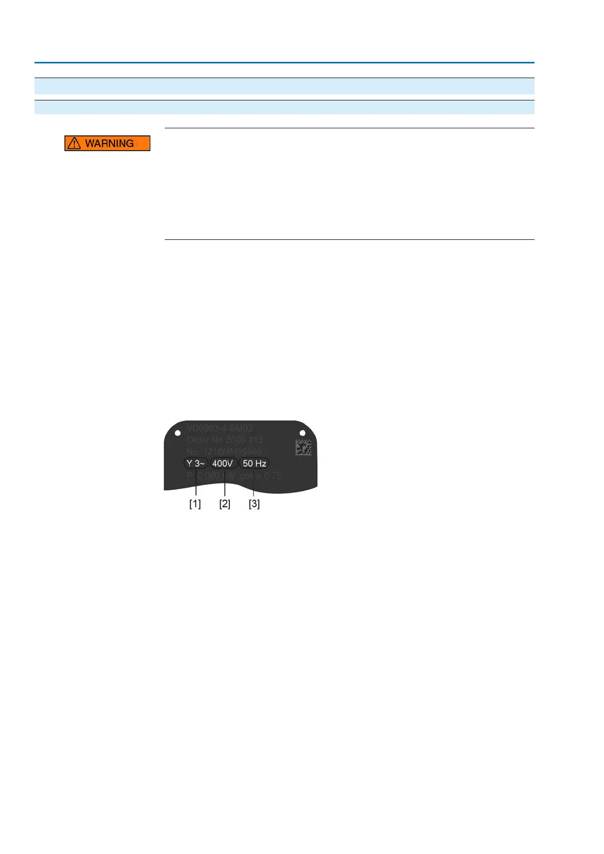
Type of current, mains voltage and mains frequency must match the data on the
actuator controls and motor name plates. Also refer to chapter <Identification>/<Name
plate>.
Figure 17: Motor name plate (example)
[1] Type of current
[2] Mains voltage
[3] Mains frequency (for 3-phase and 1-phase AC motors)
External supply of the
electronics
If electronics is supplied externally with 24 V DC, the power supply is smoothed via
an internal 1,000 µF capacitor). When selecting the power supply, care must be
taken to consider the capacitor inrush current upon powering up the unit.
Protection and sizing on
site
For short-circuit protection and for disconnecting the actuator from the mains, fuses
and disconnect switches have to be provided by the customer.
The current values for sizing the protection can be derived from the current
consumption of the motor (refer to motor name plate) plus the current consumption
of actuator controls.
We recommend adapting the switchgear sizing to the max. current (I
max
) and selecting
and setting the overcurrent protection device in compliance with the indications in
the electrical data sheet.
24
SA 07.2 – SA 16.2 /SAR 07.2 – SAR 16.2
Electrical connection AM 01.1/AM 02.1

 Loading...


