5.3. Accessories for electrical connection
5.3.1. Actuator controls on wall bracket
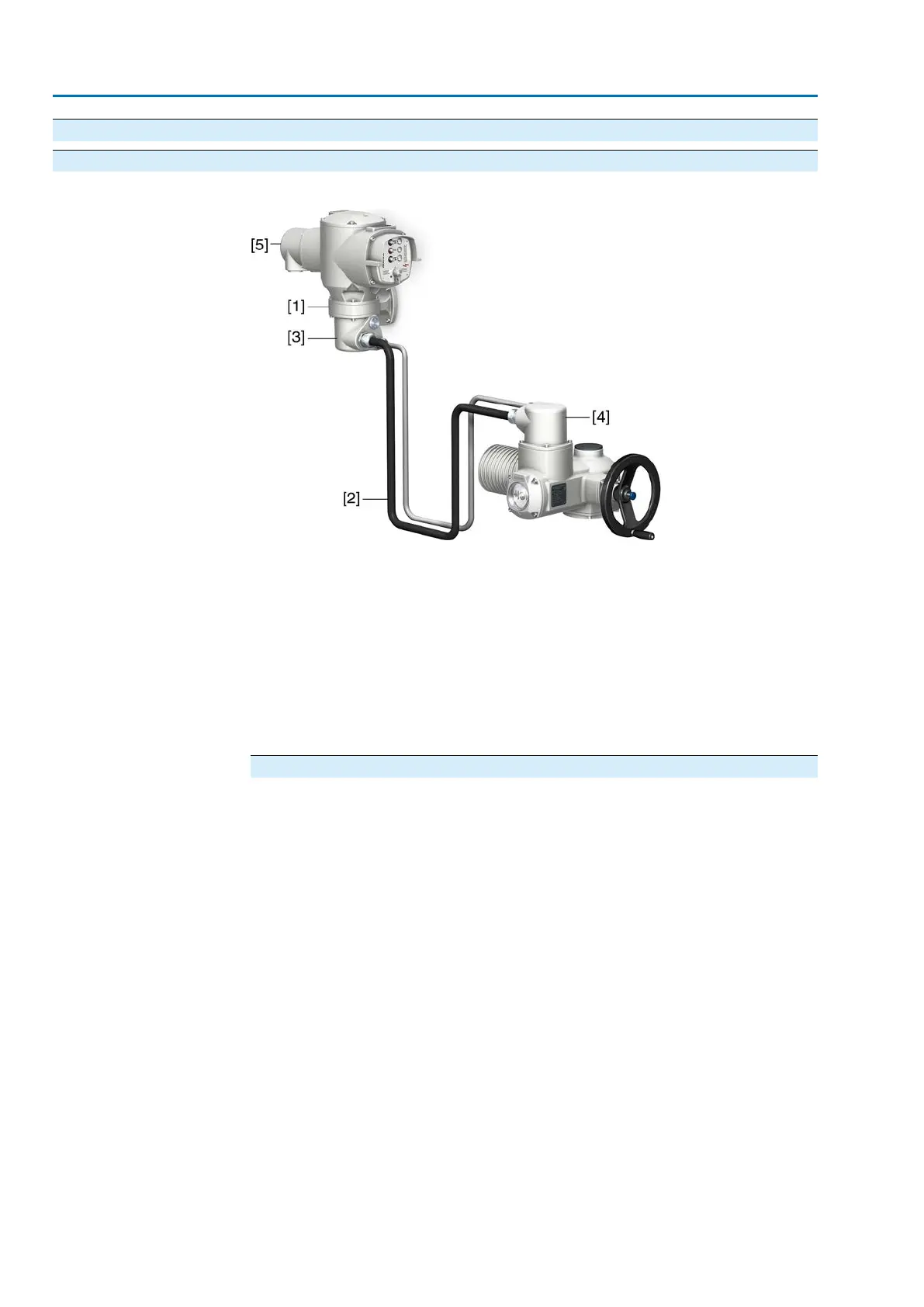
Figure 23: Setup with wall bracket (example with S electrical connection)
[1] Wall bracket
[2] Connecting cables
[3] Electrical connection of wall bracket (XM)
[4] Electrical connection of actuator (XA)
[5] Electrical connection of actuator controls (XK) - customer plug
Application
The wall bracket allows separate mounting of actuator controls and actuator.
●
If access to the mounted actuator is restricted.,
●
If the actuator is subjected to high temperatures.
●
In case of heavy vibration of the valve.
Information on installation with wall bracket
●
The permissible cable length between actuator controls on wall bracket and
the actuator amounts to 100 m maximum.
●
We recommend using an AUMA cable set "LSW".
●
If the actuator is equipped with a position transmitter (EWG, RWG, potentiomet-
er):
- Use suitable flexible and screened connecting cables.
- Earth cable shield at both ends.
●
When using connecting cables, e.g. of the heater or switch, requiring direct
wiring from the actuator to the XK customer plug (XA-XM-XK, refer to wiring
diagram), these connecting cables must be subject to an insulation test in
compliance with EN 50178. Connecting cables of position transmitters (EWG,
RWG, IWG, potentiometer) do not belong to this group.They may not be sub-
jected to an insulation test.
30
SA 07.2 – SA 16.2 /SAR 07.2 – SAR 16.2
Electrical connection AM 01.1/AM 02.1

 Loading...


