9.5. Intermediate positions: set
Actuators equipped with DUO limit switching contain two intermediate position
switches. One intermediate position may be set for each running direction.
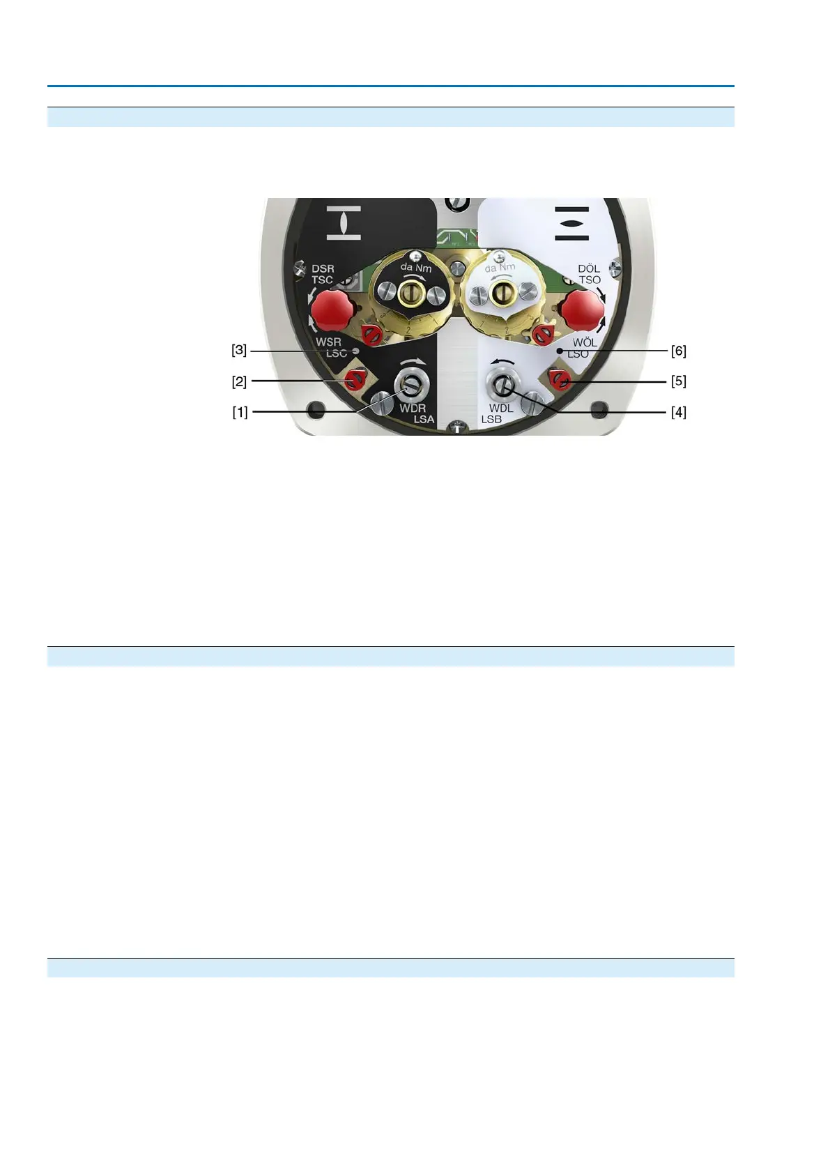
Figure 34: Setting elements for limit switching
Black section:
[1] Setting spindle: Running direction CLOSE
[2] Pointer: Running direction CLOSE
[3] Mark: Intermediate position CLOSED is set
White section:
[4] Setting spindle: Running direction OPEN
[5] Pointer: Running direction OPEN
[6] Mark: Intermediate position OPEN is set
Information After 177 turns (control unit for 2 – 500 turns/stroke) or 1,769 turns (control unit for
2 – 5,000 turns/stroke), the intermediate switches release the contact.
9.5.1. Running direction CLOSE (black section): set
1. Move valve in direction CLOSE to desired intermediate position.
2. If you override the tripping point inadvertently: Turn valve into the opposite dir-
ection and approach intermediate position again in direction CLOSE.
Information: Always approach the intermediate position in the same direction
as in later electrical operation.
3. Press down and turn setting spindle [1] with screw driver in direction of the
arrow and observe the pointer [2]: While a ratchet click is felt and heard, the
pointer [2] moves 90° every time.
4. As soon as the pointer [2] is 90° from mark [3]: Continue turning slowly.
5. As soon as the pointer [2] moves to mark [3]: Stop turning and release setting
spindle.
➥
The intermediate position setting in running direction CLOSE is complete.
6. If you override the tripping point inadvertently (ratchet click is heard after the
pointer has snapped): Continue turning the setting spindle in the same direction
and repeat setting process.
9.5.2. Running direction OPEN (white section): set
1. Move valve in direction OPEN to desired intermediate position.
2. If you override the tripping point inadvertently: Move valve in opposite direction
and approach intermediate position again in direction OPEN (always approach
the intermediate position in the same direction as in later electrical operation).
42
SA 07.2 – SA 16.2 /SAR 07.2 – SAR 16.2
Commissioning (basic settings) AM 01.1/AM 02.1

 Loading...


