3. Connect lower setpoint to customer connection XK (terminals 2/3). The lower
setpoint (0 V, 0 mA or 4 mA) is indicated on the label [5].
4. If the red LED [V10] E1/E2 <4 mA is illuminated:
4.1 Verify polarity of setpoint E1.
4.2 Check whether external load is connected to customer connection XK
(terminals 23/24) (observe max. load R
B
), or
4.3 Connect terminals 23/24 across customer connection XK (terminals 23/24).
5. Measure setpoint E1: Connect measuring device for 0 – 5 V to measuring points
[MP3/MP4].
➥
For a setpoint E1 of 0 V or 0 mA, the voltmeter shows 0 V.
➥
For a setpoint E1 of 4 mA, the voltmeter shows 1 V.
6. If measured value is not correct: Correct setpoint E1.
7. Measure actual value E2: Connect measuring device for 0 – 5 V to measuring
points [MP1/MP2].
➥
For an actual value E2 of 0 mA, the voltmeter shows 0 V.
➥
For an actual value E2 of 4 mA, the voltmeter shows 1 V.
8. If measured value is not correct: Re-set potentiometer or electronic position
transmitter and perform adjustment once again, starting from step 1.
9. Adjust positioner using potentiometer 0 [P3].
9.1 If both LEDs are OFF or the green LED [V28] is illuminated:Turn poten-
tiometer 0 [P3] slightly clockwise until the yellow LED [V27] is illuminated.
9.2 If the yellow LED [V27] is illuminated:Turn potentiometer 0 [P3] counter-
clockwise until the yellow LED [V27] goes out.Then turn potentiometer 0
[P3] slightly clockwise until the yellow LED [V27] is illuminated again.
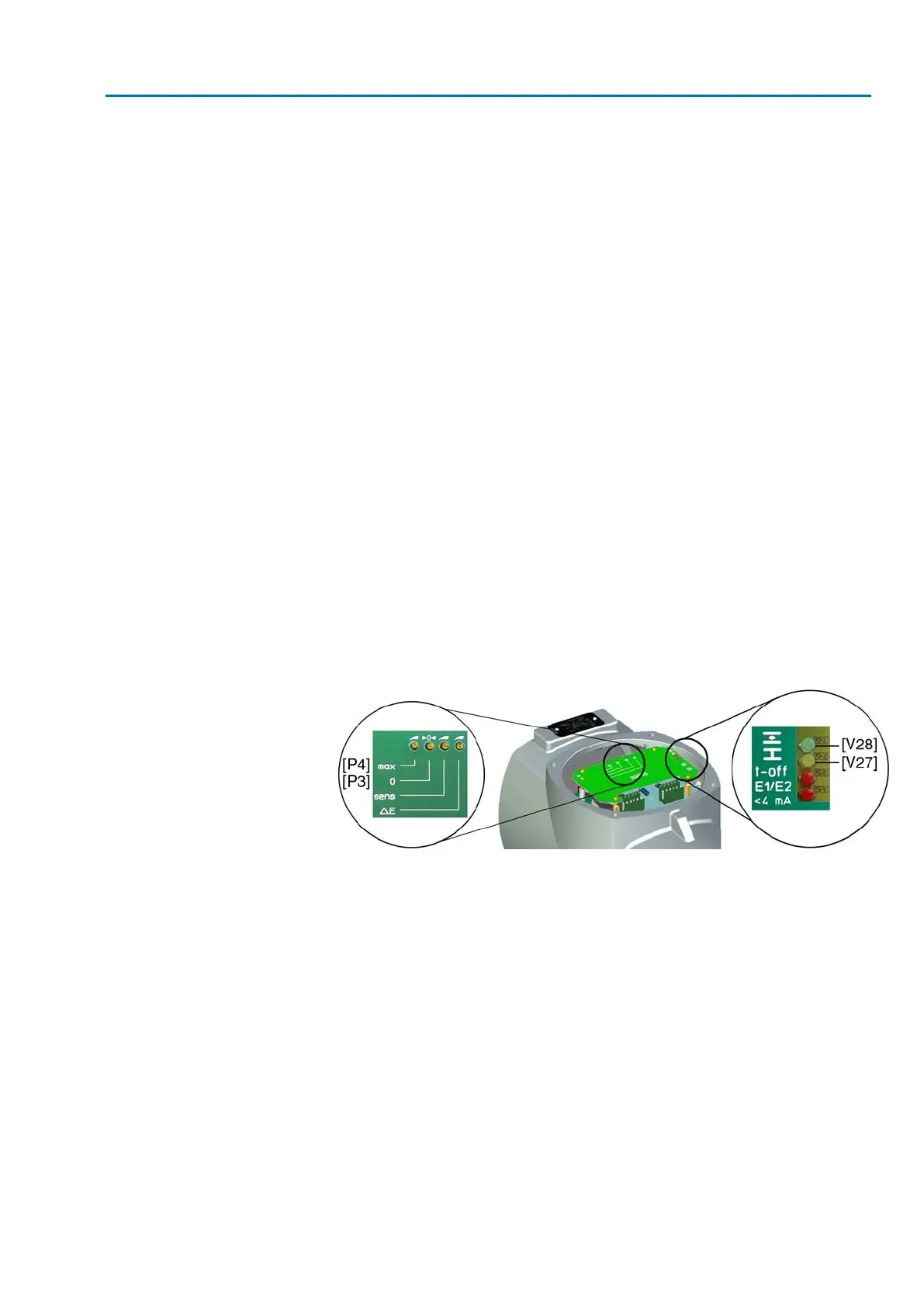
Figure 49: Electronic positioner board
[P3] Potentiometer 0
[P4] Potentiometer max
[V27] Yellow LED: End position CLOSED reached
[V28] Green LED: End position OPEN reached
➥
The setting is correct if the yellow LED [V27] is switched on when reaching end
position CLOSED.
End position OPEN
10. Move valve to end position OPEN.
11. Measure actual value E2 (measuring points [MP1/MP2]):
➥
For an actual value E2 of 20 mA, the voltmeter shows 5 V.
12. If measured value is not correct: Re-set potentiometer or electronic position
transmitter and perform adjustment once again, starting from step 1.
13. Set maximum setpoint E1 (5 V or 20 mA, refer to label [5]).
14. Measure setpoint E1 (measuring points [MP3/MP4]):
➥
For a setpoint E1 of 5 V or 20 mA, the voltmeter shows 5 V.
15. If measured value is not correct: Verify setpoint E1.
57
SA 07.2 – SA 16.2 /SAR 07.2 – SAR 16.2
AM 01.1/AM 02.1 Commissioning – controls settings

 Loading...


