4. Secure handwheel using the retaining ring supplied.
Figure 10:
4.3. Multi-turn actuator: mount to valve/gearbox
Danger of corrosion due to damage to paint finish and condensation!
→
Touch up damage to paint finish after work on the device.
→
After mounting, connect the device immediately to electrical mains to ensure
that heater minimises condensation.
4.3.1. Output drive type A
Application
●
Output drive for rising, non-rotating valve stem
●
Capable of withstanding thrust
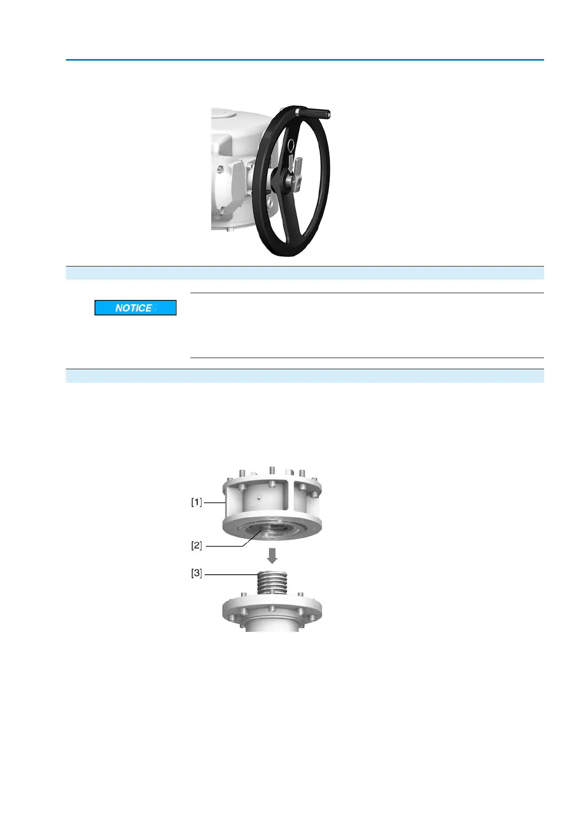
Design
Output mounting flange [1] with axial bearing stem nut [2] form one unit.Torque is
transmitted to valve stem [3] via stem nut [2].
Figure 11: Design of output drive type A
[1] Output mounting flange
[2] Stem nut with dog coupling
[3] Valve stem
15
SA 25.1 – SA 48.1 / SAR 25.1 – SAR 30.1
AM 02.1 Assembly
 Loading...


