Dead time setting
5. Set dead time using potentiometer t-off [P10]:
→
Reduce dead time: Turn potentiometer t-off [P10] counterclockwise.
→
Increase dead time: Turn potentiometer t-off [P10] clockwise.
11.8. EMERGENCY command (EMERGENCY - OPEN/EMERGENCY - CLOSE)
— (Option) —
The EMERGENCY input (refer to wiring diagram) has to be connected to the control
voltage using an NC contact (closed circuit principle). In the event of an EMERGENCY
command (removal of the signal = NC contact is operated), the actuator runs to the
preset end position:
●
EMERGENCY - CLOSE input: Actuator runs to end position CLOSED.
●
EMERGENCY - OPEN input: Actuator runs to end position OPEN.
The EMERGENCY command is effective in all three selector switch positions (LOCAL,
OFF, REMOTE).
The actuator can immediately start when switched on!
Risk of personal injuries or damage to the valve.
→
Ensure that EMERGENCY signal is present when switching on.
→
If the actuator starts to run unexpectedly: Immediately press push button Stop.
Disable EMERGENCY
command
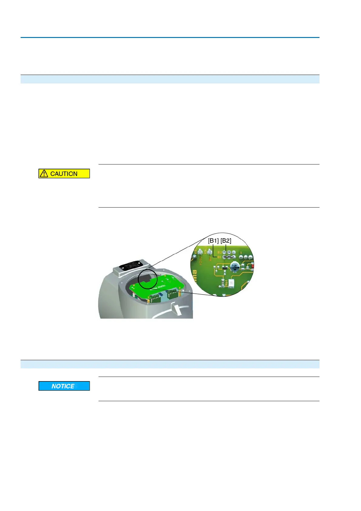
Figure 65: Interface board for available option EMERGENCY - OPEN/EMERGENCY
- CLOSE
[B1] Link available: EMERGENCY - CLOSE
[B2] Link available: EMERGENCY - OPEN
1. Remove face plate.
2. Disconnect links [B1] or [B2].
11.9. Actuator controls: close
Danger of corrosion due to damage to paint finish!
→
Touch up damage to paint finish after work on the device.
1. Clean sealing faces of housing and cover.
2. Check whether O-ring [3] is in good condition, replace if damaged.
64
SA 25.1 – SA 48.1 / SAR 25.1 – SAR 30.1
Commissioning – controls settings AM 02.1
 Loading...


