4.3.2. Output drive types B and E
Application
●
For rotating, non-rising valve stem
●
Not capable of withstanding thrust
Design
For output drive types B/B1/B2, the connection to the valve or the gearbox is made
by directly placing the multi-turn actuator hollow shaft onto the input shaft of the valve
or gearbox.
For output drive types B3/B4/E, the connection is made via output drive sleeve which
is inserted into the bore of the hollow shaft of the multi-turn actuator and fixed by a
retaining ring.
When exchanging the output drive sleeve, later retrofitting to a different output drive
type is possible
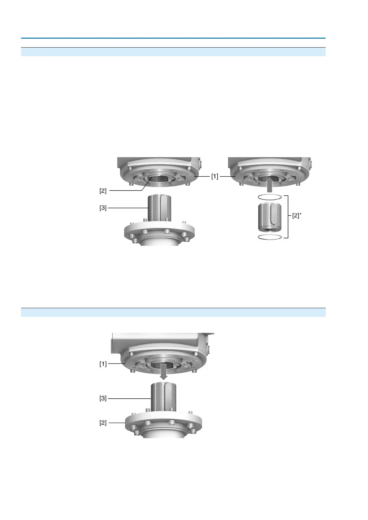
Figure 14: Output drive type B
[1] Multi-turn actuator flange
[2] For output drive types B/B1/B2 hollow shaft with keyway
[2]* For output drive types B3/B4/E, an output drive sleeve is fitted into the hollow
shaft
[3] Gearbox/valve shaft with parallel key
Information
Spigot at valve flanges should be loose fit.
4.3.2.1. Multi-turn actuator with output drive types B: mount to valve/gearbox
Figure 15: Mounting output drive types B
[1] Multi-turn actuator
[2] Valve/gearbox
[3] Valve/gearbox shaft
1. Check if mounting flanges fit together.
18
SA 25.1 – SA 48.1 / SAR 25.1 – SAR 30.1
Assembly AM 02.1
 Loading...


