5. Electrical connection
5.1. Basic information
Danger due to incorrect electrical connection
Failure to observe this warning can result in death, serious injury, or property damage.
→
The electrical connection must be carried out exclusively by suitably qualified
personnel.
→
Prior to connection, observe basic information contained in this chapter.
→
After connection but prior to applying the voltage, observe the <Commissioning>
and <Test run> chapters.
Wiring diagram/terminal
plan
The pertaining wiring diagram/terminal plan (in German or English) is attached to
the device in a weather-proof bag, together with these operation instructions. It can
also be requested from AUMA (state order number, refer to name plate) or
downloaded directly from the Internet (http://www.auma.com).
Current type, mains
voltage, mains fre-
quency
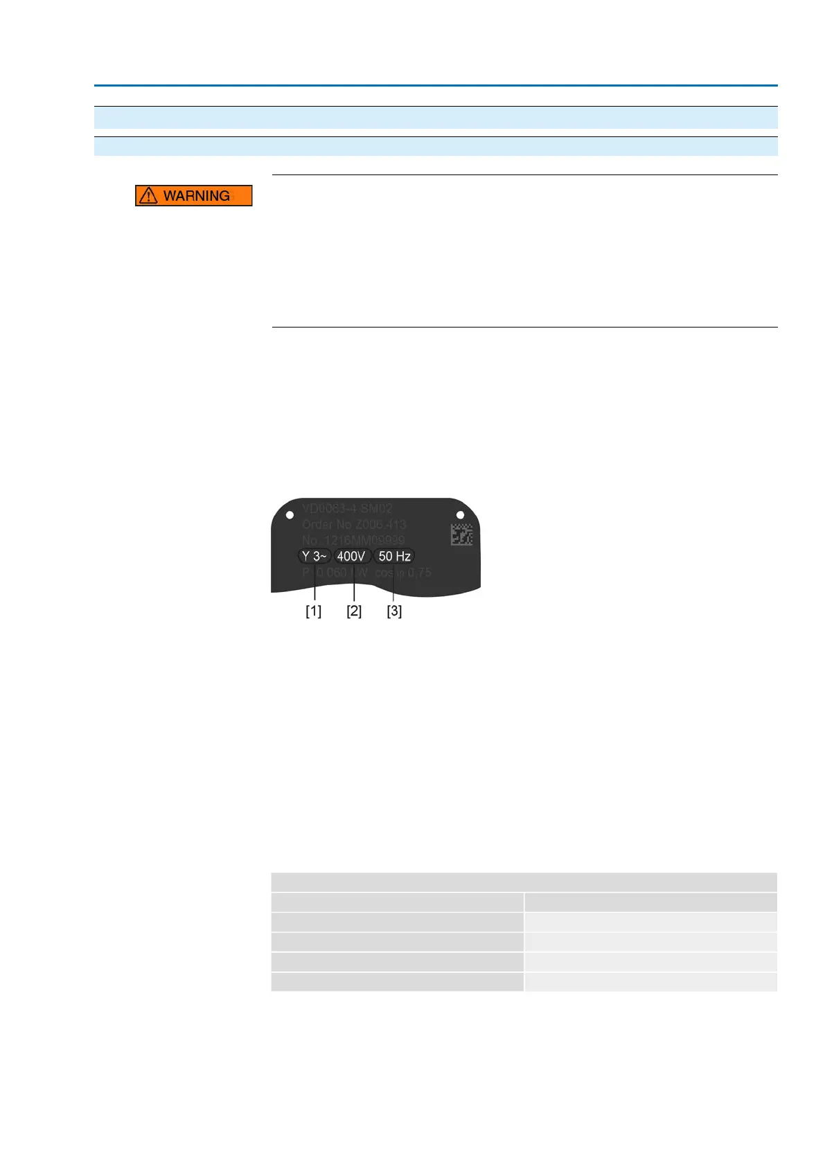
Type of current, mains voltage and mains frequency must match the data on the
actuator controls and motor name plates. Also refer to chapter <Identification>/<Name
plate>.
Figure 18: Motor name plate (example)
[1] Type of current
[2] Mains voltage
[3] Mains frequency (for 3-phase and 1-phase AC motors)
Protection and sizing on
site
For short-circuit protection and for disconnecting the actuator from the mains, fuses
and disconnect switches have to be provided by the customer.
The current values for sizing the protection can be derived from the current
consumption of the motor (refer to motor name plate) plus the current consumption
of actuator controls.
We recommend adapting the switchgear sizing to the max. current (I
max
) and selecting
and setting the overcurrent protection device in compliance with the indications in
the electrical data sheet.
Table 8:
Current consumption controls
Max. current consumptionMains voltage
575 mA100 to 120 V AC (±10 %)
275 mA208 to 240 V AC (±10 %)
160 mA380 to 500 V AC (±10 %)
500 mA24 V DC (+20 %/-15 %) and AC motor
21
SA 25.1 – SA 48.1 / SAR 25.1 – SAR 30.1
AM 02.1 Electrical connection
 Loading...


