Setting elements
The RWG is housed in the actuator switch compartment. The switch compartment
must be opened to perform any settings. Refer to <Switch compartment: open>.
Setting is made via three potentiometers [1], [2] and [3].
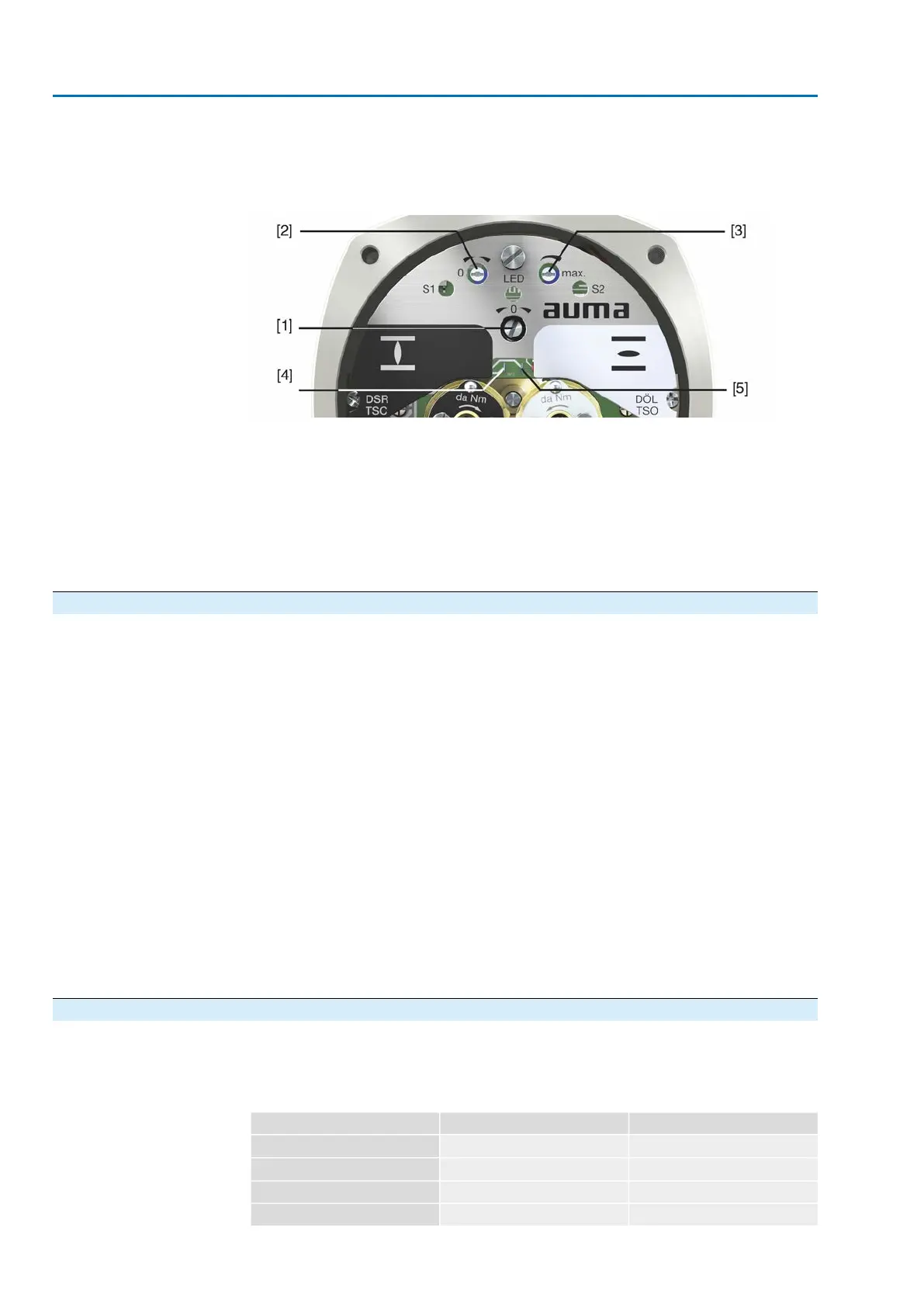
Figure 52: View on control unit when switch compartment is open
[1] Potentiometer (travel sensor)
[2] Potentiometer min. (0/4 mA)
[3] Potentiometer max. (20 mA)
[4] Measuring point (+) 0/4 – 20 mA
[5] Measuring point (–) 0/4 – 20 mA
The output current (measuring range 0 – 20 mA) can be checked at measuring points
[4] and [5].
10.2.1. Measuring range: set
For measuring range setting, voltage must be applied at the position transmitter.
1. Move valve to end position CLOSED.
2. Connect ammeter for 0 – 20 mA to measuring points [4 and 5].
3. Turn potentiometer [1] clockwise to the stop.
4. Turn potentiometer [1] slightly in opposite direction.
5. Turn potentiometer [2] clockwise until output current starts to increase.
6. Turn potentiometer [2] in opposite direction until the following value is reached:
- for 0 – 20 mA approx. 0.1 mA
- for 4 – 20 mA approx. 4.1 mA
➥
This ensures that the signal remains above the dead and live zero point.
7. Move valve to end position OPEN.
8. Set potentiometer [3] to end value 20 mA.
9. Approach end position CLOSED again and check minimum value (0.1 mA or
4.1 mA). If necessary, correct the setting.
Information
If the maximum value cannot be reached, the selection of the reduction gearing must
be checked.
10.3. EWG 01.1 electronic position transmitter
EWG 01.1 electronic position transmitter signals the remote position or the valve
position. On the basis of the actual valve position sensed by hall sensor, a current
signal between 0 – 20 mA or 4 – 20 mA is generated.
Technical data
Table 16: EWG 01.1
2-wire system3-wire and 4-wire systemsData
4 – 20 mA0 – 20 mA, 4 – 20 mAOutput current I
a
24 V DC (18 – 32 V)24 V DC (18 – 32 V)Power supply U
V
1)
20 mALED off = 26 mA, LED on = 27 mAMax. current consumption
(U
V
– 12 V)/20 mA600 ΩMax. load R
B
50
SA 25.1 – SA 48.1 / SAR 25.1 – SAR 30.1
Commissioning (optional equipment settings) AM 02.1
 Loading...


